


9
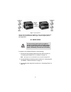
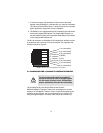
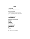
Figure 1.
Typical application
The pair of 2173 models work together to create a transparent extension
between two peered Ethernet LANs. Figure 1 shows a typical point-to-
point application.
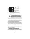
3.0 INSTALLATION
To install the 2173 Ethernet Extender, do the following:
1. Connect the line interface between the units (refer to section 3.1,
“Connecting the Twisted-Pair Line Interface” on page 10)
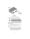
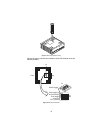
Note
See Figure 2 for the standalone unit’s rear panel arrangements.
2. Connect the Ethernet interface (refer to section 3.2, “Connecting the
10/100Base-T Ethernet Interface” on page 11).
3. Connect the power plug (refer to section 3.3, “Connecting Power” on
page 12).
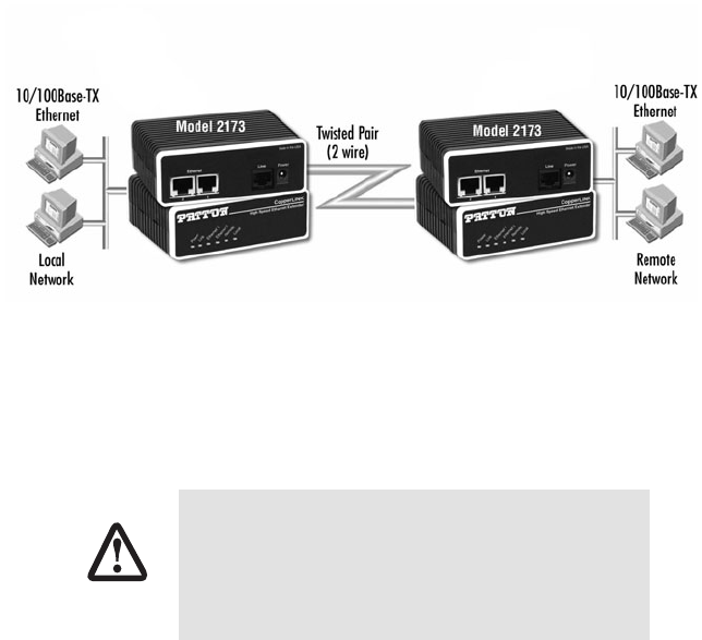
The Interconnecting cables shall be acceptable for
external use and shall be rated for the proper applica-
tion with respect to voltage, current, anticipated tem-
perature, flammability, and mechanical serviceability.
CAUTION