


11
3.1 CONNECTING THE LINE INTERFACE
The Model 2174 supports communication between two peer Ethernet
LAN sites over a distance of up to 10,000 ft (3 km) over 24 AWG
(0.5
mm) twisted-pair wire, Cat5+, or 75-ohm BNC.
Note Actual distance and link performance may vary depending on
the environment and type/gauge of wire used.
Follow the steps below to connect the Model 2174 CopperLINK Inter-
faces.
Note The Model 2174 units work in pairs. One of the units must be
configured as a (L) Local unit, and the other unit must be config-
ured as a (R) Remote unit.
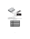
Connecting the Line Interface for Model 2174/EUI or 2174/TB
1. To function properly, the two Model 2174s must be connected
together using twisted-pair, unconditioned, dry, metal wire, between
19 (0.9mm) and 26 AWG (0.4mm). Leased circuits that run through
signal equalization equipment are not acceptable.
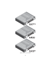
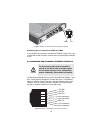
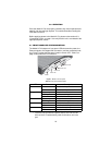
2. The Model 2174 is equipped with an RJ-45 interface jack (Figure 3) or
terminal block (Figure 4) that can be used on the CopperLINK inter-
face. The CopperLINK interface is a two-wire interface. Observe the
signal/pin relationships on the Model 2174's CopperLINK interface
jack.
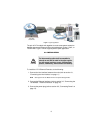
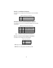
The RJ-45 connector on the Model 2174's twisted pair interface is polar-
ity insensitive and is wired for a two-wire interface. The signal/pin rela-
tionship is shown in Figure 3.
Figure 3. Model 2174 (RJ-45) twisted pair line interfac.
The Interconnecting cables shall be acceptable for
external use and shall be rated for the proper applica
-
tion with respect to voltage, current, anticipated tem-
perature, flammability, and mechanical serviceability.
CAUTION
1 (no connection)
2 (no connection)
3 (no connection)
4 (RING)
5 (TIP)
6 (no connection)
7 (no connection)
8 (no connection)
1
2
3
4
5
6
7
8