


2.0 GENERAL INFORMATION
Thank you for your purchase of this Patton Electronics product.
This product has been thoroughly inspected and tested and is warrant-
ed for One Year parts and labor. If any questions or problems arise
during installation or use of this product, please do not hesitate to con-
tact Patton Electronics Technical Support at (301) 975-1007.
2.1 FEATURES
• Synchronous network data rate of 2.048 Mbps
• Four selectable terminal rates: 256 kbps, 512 kbps,
1.024 Mbps and 2.048 Mbps
• Supports X.21/EIA-530 (RS-422) and V.35 terminal interfaces
• Both 75 ohm (BNC) and 120 ohm (modular) network terminations
• Internal or receive loop (network) clocking
• Loopback test modes
• Front panel LED indicators for power, network,
master clock and test loop
2.2 DESCRIPTION
The Patton Model 2703 G.703/E1 Digital Modem performs sev-
eral jobs: As a
modem
, the Model 2703 receives unstructured, syn-
chronous 2.048 Mbps data from a G.703 network and sends it to a
router, bridge, multiplexer or other device. As an
interface converter
,
the Model 2703 accepts 120 Ohm twisted pair or 75 Ohm dual coax
network connections (both types of interfaces provided). Then it con-
verts the signals to X.21/EIA-530 (RS-422) or V.35 (switchable) on an
UD-26 connector.
As a
Rate Adapter
, the Model 2703 lets a lower bandwidth
device–256 kbps, 512 kbps, or 1.024 Mbps–connect to a 2.048 Mbps
G.703 link. The Model 2703 supports internal or network (receive
loop) clocking. Loopback test is built-in, and front panel LEDs monitor
power, network, master clock and test loop. Several power supply
options are available.
3
3.0 CONFIGURATION
The Model 2703 is equipped with two sets of eight DIP switches
(externally accessible), as well as seven jumpers (internal). These DIP
switches and jumpers allow configuration of clocking, data rate, test
and terminal interface options. The Model 2703 is also equipped with
an internal switch that allows selection of 115 or 230 VAC power inputs
(Note: this switch is not present in Models 2703-UI and 2703-DC).
This section describes switch and jumper locations and explains all
possible configurations.
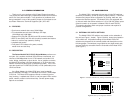
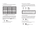
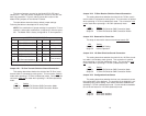
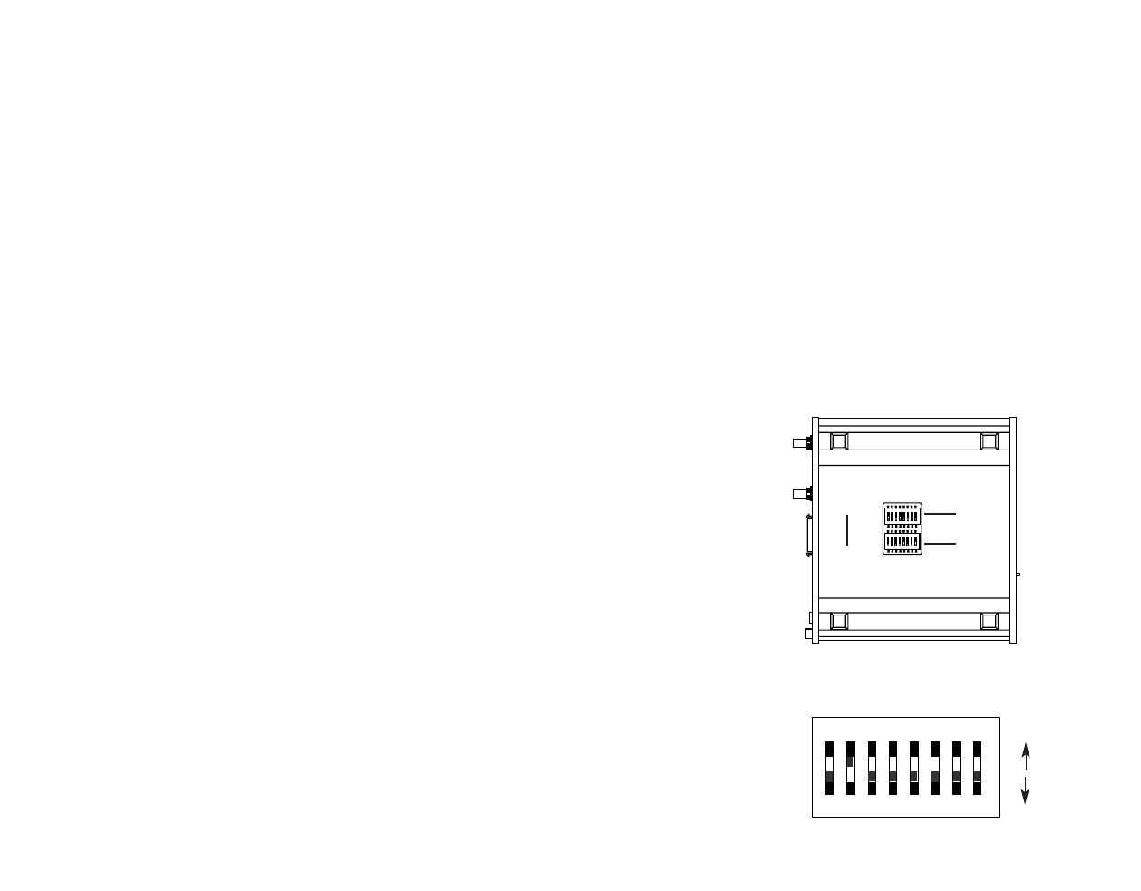
3.1 EXTERNAL DIP SWITCH SETTINGS
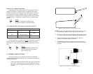
The Model 2703’s DIP switches are located on the underside of
the unit (see Figure 1, below). Figure 2 (below), shows the orientation
of the switch set. All possible settings for the Model 2703’s DIP
switches are presented in the summary table and descriptions on the
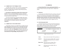
following pages. The switches are grouped into two eight-switch sets,
and are externally accessible from the underside of the Model 2703
(See Figure 1).
4
Figure 2. Close up of configuration switches
OFF
12345678
DHS-8
OFF
ON
Figure 1. Underside of Model 2703, showing external DIP switch locations
ON
12345678
ON
12345678
Switch
Set “S1”
Switch
Set “S2”
1 2 3 4 5 6 7 8
ON
ON
OFF