Switch Set S1
The configuration switches on S1 set clocking, rate adaptation,
loopback enable, and data invert. The default settings are
summarized in the table below.
S1-1: Master/Slave Clock
The setting for switch S1-1 determines whether the Model 2703-
X21 provides the master clock, or is slaved to another clock source.
S1-1
Setting
On Model 2703-X21 is master
Off Model 2703-X21 is slave, (clock is recovered
from the network)
3.0 CONFIGURATION
The Model 2703-X21 is equipped with one DIP set containing eight
switches (externally accessible), as well as seven jumpers (internal).
These switches and jumpers allow configuration of clocking, data rate,
and test options. The Model 2703-X21 is also equipped with an internal
switch that allows selection of 115 or 230 VAC power inputs (Note: this
switch is not present in Models 2703-X21-UI and 2703-X21-DC). This
section describes switch and jumper locations and explains all possible
configurations.
3.1 EXTERNAL DIP SWITCH SETTINGS
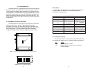
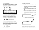
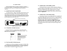
The Model 2703-X21’s DIP switch set is located on the underside
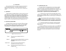
of the unit (see Figure 1, below). Figure 2 (below), shows the
orientation of the switch set. All possible settings for the Model 2703-
X21’s switches are presented in the summary table and descriptions on
the following pages. If you have additional questions regarding
configuration, contact Patton Technical Support at (301) 975-1000.
3 4
Figure 2. Close up of configuration switches
OFF
12345678
DHS-8
OFF
ON
Figure 1. Underside of Model 2703, showing external DIP switch location
S1 SUMMARY TABLE
Position Function Factory Default
S1-1 Clock Master/Slave On Master
S1-2 Rate Adaptation Off
S1-3 Rate Adaptation Off
S1-4 Test Enable Off Front Panel
S1-5 Data Inversion Off Not Inverted
S1-6 Not Used Off N/A
S1-7 Not Used Off N/A
S1-8 Not Used Off N/A
}
2.048 Mbps
S1
1 2 3 4 5 6 7 8
ON


