


IPLink 2800 Quick Start Guide
3
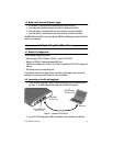
1.3 Models with internal DC power supply
1.
Strip insulation 1/4-inch from the wires connecting the power source to the IPLink.
2.
Connect the ground terminal from the power source with to the
E
terminal on the IPLink.
3.
Connect the negative (-) terminal from the power source with to the (
-
) terminal on the IPLink.
4.
Connect the positive (+) terminal from the power source with to the (
+
) terminal on the IPLink.
The
PWR
LED blinks as the IPLink is powering up. When the
PWR
LED stops blinking and remains lit, the IPLink is
ready for user configuration.
2.0 Setting the IP address
2.1 Default IP configuration
The factory default IP settings are as follows:
•
LAN port(s) (green, ETH 0/1): IP address: 192.168.1.1, netmask: 255.255.255.0
•
WAN port (red, ETH 0/0): IP address and netmask: DHCP client
•
A DHCP server with address space 192.168.1.10–192.168.1.99 (netmask: 255.255.255.0) is running on the
LAN ports
•
Both Ethernet ports are pre-configured and active
If these addresses conflict or do not match with your network they must be changed. Contact your network
administrator if you are not sure which IP address to use in your installation.
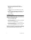
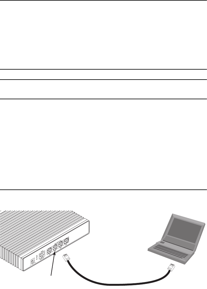
2.2 Connecting to the PC and logging in
1.
To access the IPLink configuration, connect a PC with an Ethernet port to one of the LAN ports (green)
(see
figure 1
). Use the black Ethernet cable included with your IPLink for this purpose.
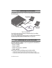
Figure 1.
Connecting to the PC’s ENET port
2.
Set your PC’s TCP/IP configuration to DHCP to automatically receive an IP address from the IPLink.
PC
(DHCP, for example:
192.168.1.10/24
)
Connect to Ethernet LAN
ports 0/1—0/4
IPLink 2800
192.168.1.1/24
Ethernet port