


5.0 OPERATION
Having connected the host and terminal cables to the Model 457B,
you are ready to operate the unit. This section tells how to power the
unit, and how to read the port status LED indicators.
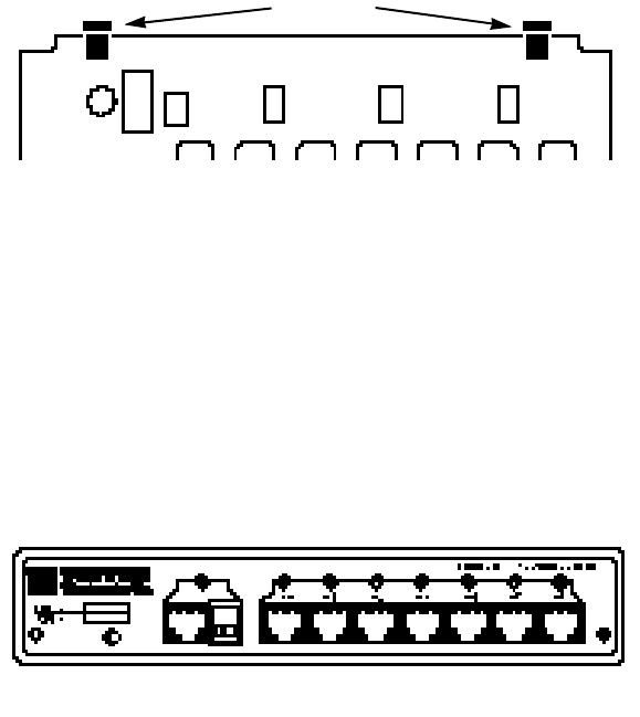
5.1 POWER UP
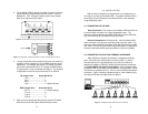
There is no power switch on the Model 457B. To apply power to
the unit, plug the AC adapter into one of the two rear jacks (see figure
5, below) and then into a wall outlet. The front panel "Power" LED
should glow yellow when power is applied. The port status LEDs
should be off if the host and terminals are not yet powered up.
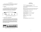
5.2 "PORT STATUS" LED INDICATORS
As figure 6 (below) illustrates, there is a status LED for each port
on the Model 457B. Having followed the normal start-up procedures for
your system, the host port LED should glow faintly red and each active
terminal port's LED should glow faintly green. Inactive ports should not
show any LED activity. When data activity is occurring on a port, its
LED should glow brightly. Failure of a particular port's LED to behave
as described here may indicate a problem with the cable connection or
with the host/terminal hardware.
APPENDIX A
SPECIFICATIONS
Connectors: Host port—terminal block and RJ-45 jack
Terminal ports—RJ-45 jack
Applicable Hardware: IBM AS/400 and System 34/36/38 compatible
hosts and terminals
Range: 2250 ft (24 AWG unshielded twisted pair) between the hub and
each connected device; maximum host-to-terminal range is 4500 ft
Transmission Protocol: Transparent to user
Link-to-Data Isolation: 500 Volts RMS
Operating Temperature: 40
°
F to 130
°
F (5
°
C to 54
°
C)
Storage Temperature: 0
°
F to 185
°
F (-17
°
C to 85
°
C)
Humidity: Up to 95% non-condensing
Dimensions: 7.25"w x 1.6"h x 3.75"d
Weight: 0.9 lb
Power Requirements: Regulated 5VDC @ 250 mA
87
Figure 5. Rear panel of Model 457B, showing power jacks
Figure 6. Front panel of Model 457B, showing LED indicators
Power Jacks