


2.0 GENERAL INFORMATION
Thank you for your purchase of this Patton Electronics product.
This product has been thoroughly inspected and tested and is
warranted for One Year parts and labor. If any questions arise during
installation or use of the unit, contact Patton Electronics Technical
Support at (301)975-1000.
2.1 PRODUCT DESCRIPTION
The Patton Model 504 & 505 Surge Protected DB-25 to
Modular Adapters allow you to simplify cabling connections and
protect your RS-232 or RS-422 DB-25 equipment at the same time.
Each adapter is custom wired according to your pin-out diagram (no
“standard” wiring). Up to 1500 Watts of surge protection per modular
pin is provided. On the Models 504, an RJ-11 jack is used, and up to 6
pins may be protected. On the Model 505, an RJ-45 jack is used, and
up to 8 pins may be protected. Both the Model 504 and 505 employ
Silicon Avalanche Diodes for superior transient protection. You may
specify a clamping voltage of 27V for RS-232 applications or 6.8V for
RS-422 applications. Surges are shunted safely to chassis ground
through the D-shell connector. Male or female DB-25 connectors are
available.
Warning: These products will not provide complete protection
should your equipment be subject to a direct lightning hit.
2.2 SURGE PROTECTION BENEFITS
The method of surge protection used in the Models 504 & 505
adds four benefits to your system:
1)
High Surge Capacity
. The Models 504 & 505 dissipate up to
1500 Watts per wire in 1.0 millisecond.
2)
Quick Response.
The Models 504 & 505 have fast response
times (1 pS at the component level; 0.5 µS installed). Transient
surges are clamped at 27V for RS-232 and 6.8V for RS-422.
3)
Low Impedance.
The Models 504 & 505 add minimal load to
your system--about the same as a gender changer.
4)
Open Failure.
The Models 504 & 505 fail “open” if your system
experiences a severe transient or power fault above the rated
voltage of the protector. This means that data and surge energy is
shunted directly to chassis ground, rather that being allowed to
flow throughout the system.
3.0 MODEL 504 & 505 INSTALLATION
The Patton Models 504 & 505 are simple to install and require no
user configuration. Follow these installation steps:
1) Be sure the metal D-sub connector on the device you are
protecting is connected to frame ground. If not, see step 4,
below.
2) Plug the DB-25 connector of the Model 504 or 505
directly
into
the DB-25 Serial port of the device you are protecting. Use of
a serial cable reduces the effectiveness of the protection you
would otherwise receive.
3) Plug your modular cable into the jack on the Model 504 or 505.
If you have a Model 504, the cable must be terminated with an
RJ-11 plug. If you have a Model 505, the cable must be
terminated with an RJ-45 plug.
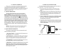
4) To provide an alternate ground connection, use the short strap
supplied with the unit. Connect one loop to the device chassis
(or other chassis ground) and the other loop to the Model 504
or 505 as shown below.
Connect to
Chassis
Ground
Connect to
D-Sub
Screw
Figure 1. How to Connect the Patton Model DB-25 to Your PC, Modem or Printer
3 4