


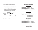

3.0 INSTALLATION
The Patton Model 510/511/512 is easy to install. The following
instructions will clearly explain each step:
1. Connect the unit between the data line and the equipment that
is to be protected. We use a bi-directional circuit, so you don't
need to worry about an input side and an output side.
2. Connect the braided ground strap directly to a chassis ground
connection on the protected device. If you are unsure where
to locate a frame ground connection on your equipment, be
sure to consult the equipment’s user manual or contact the
manufacturer—the ground connection is critical for proper
operation of the Model 510/511/512.
APPENDIX A
PATTON MODEL 510/11/12 SPECIFICATIONS
Models 510/6 and 510/25
Connectors: RJ-11 (4-wire)
Pins Wired/Protected: All 4 pins on RJ-11 interface
Surge Capacity: 600 W for 1 mS
Response Time (RS-422): Clamped to + or - 6 volts after 0.5 µS,
200 Amps with a 8/20 µS pulse
Response Time (RS-232): Clamped to + or - 25 volts after 0.5 µS,
200 Amps with a 8/20 µS pulse
Models 51
1/6 and 511/25
Connectors: RJ-12 (6-wire)
Pins Wired/Protected: All 6 pins on RJ-12 interface
Surge Capacity: 600 W for 1 mS
Response Time (RS-422): Clamped to + or - 6 volts after 0.5 µS,
200 Amps with a 8/20 µS pulse
Response Time (RS-232): Clamped to + or - 25 volts after 0.5 µS,
200 Amps with a 8/20 µS pulse
Models 512/6 and 512/25
Connectors: RJ-45 (8-wire)
Pins Wired/Protected: All 8 pins on RJ-45 interface
Surge Capacity: 600 W for 1 mS
Response Time (RS-422): Clamped to + or - 6 volts after 0.5 µS,
200 Amps with a 8/20 µS pulse
Response Time (RS-232): Clamped to + or - 25 volts after 0.5 µS,
200 Amps with a 8/20 µS pulse
Copyright © 1999
Patton Electronics Company
All Rights Reserved
Model 510/11/12
Surge Protector
Connection to
frame ground
Output to protected
equipment
UTP input
from network
Figure 1. How to Connect the Model 510/11/12 Braided Ground
Strap to the Chassis Ground Connection
3
4