


3.0 INSTALLATION
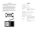
The Patton Model 535 and 536 are very easy to install: no special
cables or batteries are needed. Simply unplug the cable from the AUI
port and insert the unit between the cable and the port as shown in the
appropriate diagram below.
If you are installing the Model 536, you will also need to
connect the braided ground strap. Connect this strap directly to a
frame ground connection on the protected device. If you are unsure
where to locate a frame ground on your equipment, consult the
equipment’s user manual or contact the manufacturer—the ground
connection is critical for proper operation of the Model 536.
Note: The Model 535 shunts surge current to chassis ground
through the
connector shells
on both ends. If you have any questions
as to whether your hardware is grounded properly, consult the
manufacturer's user manual(s).
APPENDIX A
SPECIFICATIONS
Protocol/Application: Token Ring
Industry Standard: IEEE 802.5
Maximum Signal Rate: 4 Mbps / 16 Mbps
Connectors: One male, one female DB-9 connector
(Model 535); two female RJ-45 connectors
(Model 536)
Wires Protected: 1, 5, 6, 9 (535); 3, 4, 5, 6 (536)
Operating Bandwidth: 60MHZ Max. (535); 130MHZ (536)
Maximum Capacitance: 45pF (535); 19pF (536)
Peak Surge Current: 500A (535); 1000A (536)
Clamp Voltage: 27V @ 100A, line to ground (535); 5V @
100A, line to shield (536); (ratings apply to
transient, non-continuous current)
Grounding: Via connector shells (535); via grounding
strap (536)
Size: 2.69”l x 1.22”w x 0.69”h (535); 3.05”l x
1.68”w x 0.81”h (536)
3 4
Figure 1. Connecting the Model 535
Figure 2. Connecting the Model 536
Model 535 802.5 Token
Ring Protector (DB-9)
Gaithersburg, Maryland
MODEL 536
802.5 Toeken Ring Surge
Protector (UTP)
S/N 1009