


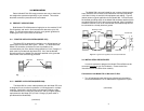
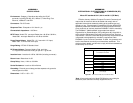
2. Install the Model 570/580 between the incoming UTP line and the
protected equipment (see Figure 3, below). This installation
requires a straight through Cat-5 patch cable with modular RJ-45
connectors (supplied with unit). Note: It doesn’t matter which end
of the Model 570/580 plugs into which cable.
3. Locate a metal chassis ground on the equipment to be protected.
This is often a hex screw on a D-shell or AUI connector.
Sometimes a metal back panel is attached by screws, one of which
can be used for chassis grounding. If you cannot locate a chassis
ground connection on your equipment, contact Patton Technical
Support at (301) 975-1000 to discuss an alternative grounding
solution.
4. Connect the braided ground strap directly to the chassis ground
connection you have located (see Figure 3, above). The best way
to make this connection is to attach the braided metal strap using a
hex nut or screw on your device.
Caution: Surge energy may run both directions on the ground
strap. To provide the best protection, it is essential that the ground
strap on the Model 570/580 be connected to the chassis ground of
the protected device. Do not lengthen the ground strap of the
Model 570/580 or connect to a ground other than chassis ground
unless instructed to do so by Patton Technical Support.
Connection of the Model 580 at a Barrier (Wall, Bldg Entrance, etc.)
1. Disconnect the UTP cable from the wall jack or patch panel jack.
2. Install the Model 580 between the UTP line and the jack. This
installation requires a straight through Cat-5 patch cable with
modular RJ-45 connectors (supplied with unit). Note: It doesn’t
matter which end of the Model 580 plugs into which cable.
3. Locate an electrical ground nearest the jack. Often this will be on
an electrical panel or sub panel. If you cannot locate a nearby
electrical ground, contact Patton Technical Support at
(301) 975-1000 to discuss an alternative grounding solution.
4. Connect the braided ground strap directly to the electrical ground
you have located. The best way to make this connection is to
attach the braided metal strap to a metal panel or wallplate screw
using a hex nut or screw.
Caution: Surge energy may run both directions on the ground
strap. To provide the best protection, it is essential that the ground
strap on the Model 580 be connected to an electrical ground.
5
6
Connection to
chassis ground
Cat-5 patch cable to
protected equipment
(6 inches or less)
Cat-5 input
from network
Figure 3. Installation of Model 570/580 Surge Protectors.