


3.2 INSTALLATION PROCEDURES
In order to operate as designed, the Model 57x and 58x must be
connected correctly
to your Cat-5 network. For the safest installation,
please read all the instructions below and follow them very carefully.
3.2.1 Connecting the Model 57x or 58x to an I/O Port
1. Turn off equipment power and disconnect the existing connection
between the UTP cable and the equipment’s I/O port.
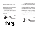
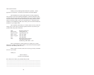
2. Install the surge protector between the incoming UTP line
and the protected equipment, as in Figure 3, below. This
installation requires a straight through Cat-5 patch cable with
modular RJ-45 male connectors . Use shortest length possible.
Note: The ports are bidirectional. Therefore, the input cable must
be directly across from the output cable.on the Model 57/58x.
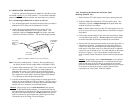
3. Locate a metal chassis ground. This is often a hex screw on a D-
shell or an AUI connector. Sometimes, a metal backpanel is
attached with screws, one of which can be used with chassis
grounding. If you cannot locate a chassis ground equipment on
your equipment, contact Patton Technical Support (See Section
1.1) to discuss an alternate grounding solution.
4. Connect the braided ground strap directly to chassis ground con-
nection you have located (see Figure 3, above). The best way to
make this ground connection is to attach the braided metal strap
using a hex nut or screw on your protected device.
Caution
: Surge energy may run both directions on the ground
strap. To provide the best protection, it is essential that the sup-
plied ground strap on the Model 57x/58x is connected to the chas-
sis ground of the protected device. Do Not lengthen the ground
strap or connect to a ground other than chassis ground unless
instructed to do so by Patton Technical Support.
3.2.2 Connecting the Model 58x at a Barrier (Wall,
Building, Entrance, etc.)
1. Disconnect the UTP cable from the wall jack or patch panel jack.
2. Install the Model 58x between the UTP line and the jack. This
installation requires a straight through Cat-5 patch cable with
modular RJ-45 male connectors.
Note: It doesn’t matter which port the UTP cable plugs into on the
rack, ss long as the input is directly above or below the correspon-
ding output.
3. Connect the ground braid(s) to the rack frame according to Figure
4 connected to earth ground. Do not lengthen the ground strap
or section describes connection procedures for both models.
4. Connect the rack structure frame directly to the earth ground if it is
not already connected. The best way to make this ground con-
nection is to attach a thick braided metal strap earth ground to a
metal panel, a wall plate screw or an electrical panel or subpanel,
using a hex nut or ground screw. Pay close attention to the impor-
tant note in Figure 4. If you cannot locate a nearby electrical
ground, contact Patton Electronics Technical Service (see Section
1.1)
Caution
: Surge energy may run both directions on the ground
strap. To provide the best protection, it is essential that the sup-
plied ground strap on the 57x/58x is connected to the chassis
ground of the protected device. Do not lengthen the ground strap
or connect to a ground other than a chassis ground unless
instructed to do so by Patton Technical Support.
6
Figure 3. Installation of Model 57x /58x Surge Protectors.
5
Cat. 5 input
from network
Cat. 5 patch
cable to pro-
tected
equipment
Connection
to chassis
ground