


7622 Rickenbacker Drive
Gaithersburg, MD 20879 USA
Phone +1-301-975-1000
Fax +1-301-869-9293
E-mail sales@patton.com
Web www.patton.com
07MD6511-DS3
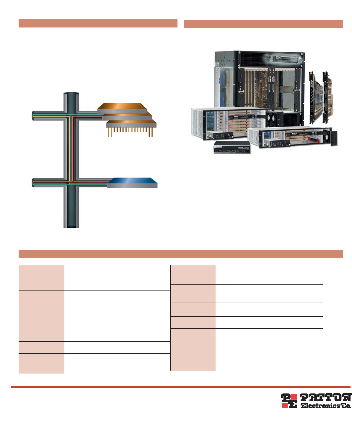
Backplane Diagram
Patton is a registered trademark and IPLink is a trademark of Patton Electronics Company in the
United States and other countries.
Specifications
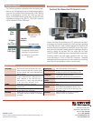
ForeFront System Elements
ForeFront Next Generation DSL Network Access
The ForeFront architecture guarantees total non-blocking oper-
ation for any TDM application and for Packet switching applica-
tions over the redundant Packet Switching Bus (PSB). With the
ability to simultaneously transmit and receive on both full-
duplex 10/100/1000 Ethernet up-link ports, the 6511RC offers
unparalleled switching to any DSL, E1, STM-1/OC-3 media as
well as redundant PSB and TDM buses.
Patton’s ForeFront Access Solutions for DSL address the new point-
of-presence requirements demanded by today’s providers operating
IP and TDM networks. Using a modular approach, the ForeFront AIS
includes all system components to provide DSL access. Fully redun-
dant power and integrated cooling enable the lightweight chassis to
scale for density and services. DSL line cards offer the latest
ITU/ETSI G.SHDSL technology for true standards based connectivity.
Grooming facilities and high speed softswitch allow any-to-any
cross-connecting to T1/E1s or STM-1/OC-3 interfaces. Integrated
management gives command over the entire system end-to-end and
offers tools for fault detection, isolation, and correction.
nxT1/E1
TDM
Egress
High-Speed
Trunk Egress
IP/Packet
&
STM-1/OC-3
Complete user flexibility allows
switching of any time slot from
any interface to any port within
the system.
DSL Concentrator
3096RC T-DAC
6511 Matrix Switch
DSL Concentrator
DSL Concentrator
G.SHDSL Access
Connections
Timeslot Mapper
TDM/PSB
Backplane
DS1-SF, SLC-95, ESF, E1–G.704 basic, CRC-4 multi-
frame (G.706 framing), DS3–M23, C-bit parity formats,
E3–G.751, G.832 E3, STM-1–G.707, SONET/STS-3–Per
ANSI T1.105-2001
DS1–VT1.5 -> STS-1 SPE, TU-11 -> STM1/VC3, TU-11
-> TUG3 -> STM1/VC4, TU12 -> STM1/VC3, TU-12 ->
TUG3 -> STM1/VC4; E1–VT2 -> STS1 SPE, TU-12 ->
STM-1/VC3, TU-12 -> TUG3 -> STM-1/VC4; DS3–DS3
-> VC3 -> AU3 -> STS-1 SPE; STM-1 –G.707;
SONET/STS3– Per ANSI T1.105.02-2001
STM-1–G.813; STS-3 - ANSI T1.101-1999, T1.105.09-
1995, G4-1244
G.821 & G.826 (ES, SSES, US, EB, and BBE; T1.231 &
GR-253-CORE ES, SES, US and SEFS
PRBS per ITU-T 0.151 & 0.152; DS3/E3 Diagnostic &
Line Loopback; DS2 Demux Loopback; T1/E1 Diagnostic
& Loopback
Dual 10/100/1000 Base-T (RJ-45 connector)
Single mode dual SC fiber (20km) per G.957 using 1310
nm lasers per G.652 or Dual 75-Ohm BNC per G.703
LEDs for power, CPU, Dual Ethernet, test mode, egress
synchronization, egress trunk status
HTTP, SNMP, TELNET Ethernet, RS-232 Console Port,
SYSLOG Client, Remote Software Upgrade via FTP
Configurable alarms; Remote SNMP Traps; Front Panel
LEDs
Safety: UL/CSA per UL1950 (METS) Canadian cMET and
CS-03. EMC Directive 89/336/EEC, FCC Part 15, CE
Mark, CTR12, CTR13 FCC Part 68. Laser Safety: Class
1, IEC-825-1, 1993
Operating temperature: 14 to 140°F (0 to 60°C);
Humidity: 5 to 90%, non-condensing
Line Framing
Mapping
Clocking
Error Counts
Line Testing
Ethernet Ports
STM-1/STS-3 Ports
LED Indicators
Management
Services
Alarm Reporting
Compliance
Environment