


2
1.0 Warranty Information .................................................................. 3
1.1 Radio and TV Interference............................................................ 3
1.2 CE Notice...................................................................................... 4
1.3 Service.......................................................................................... 4
2.0 General Information..................................................................... 5
2.1 Features........................................................................................ 5
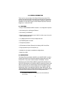
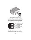
2.2 Description.................................................................................... 5
3.0 Installation.................................................................................... 7
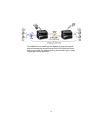
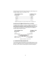
3.1 Connecting the Twisted-Pair Line Interface.................................. 7
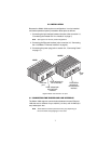
3.2 Connecting the 10/100Base-T Ethernet Interface ........................ 9
Connecting the 10/100Base-T Ethernet Port to a Hub................. 9
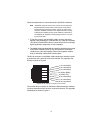
Connecting the 10/100Base-T Ethernet Port to a PC (DTE)...... 10
3.3 Connecting the POTS/ISDN line................................................. 10
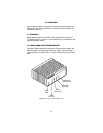
3.4 Connecting Power ...................................................................... 11
4.0 Operation.................................................................................... 12
4.1 Power Up.................................................................................... 12
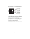
4.2 Front Panel LED Status Monitors ............................................... 12
A Specifications ............................................................................ 14
A.1 LAN Connection ..........................................................................14
A.2 Transmission Line ........................................................................14
A.3 VDSL Line Rate ............................................................................14
A.4 Actual Data Rate ..........................................................................14
A.5 VDSL Distance .............................................................................14
A.6 VDSL Surge Suppressor ..............................................................14
A.7 LED Status Indicators ..................................................................14
A.8 Power Supply ...............................................................................14
A.9 Temperature Range .....................................................................14
A.10 Humidity .......................................................................................14
A.11 Dimensions ..................................................................................14
B Model 1058 Series Factory
Replacement Parts and Accessories....................................... 15
C Model 1058 Series Interface Pin Assignment ......................... 16
C.1 10/100Base-T Interface: ..............................................................16
RJ-45.......................................................................................... 16
C.2 VDSL Interface: ............................................................................16
RJ-45.......................................................................................... 16
Terminal Block............................................................................ 16
C.3 POTS/ISDN Interface: ..................................................................16
RJ-45.......................................................................................... 16