


14
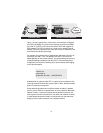
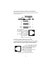
Connecting the Twisted Pair (120 ohm) to the G.703 Network
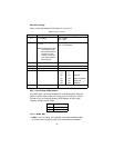
Refer to the pinout and signals chart in Figure 6 to connect the 120-ohm
G.703 network channel.
Figure 6.
G.703 120-ohm connection.
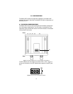
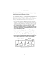
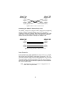
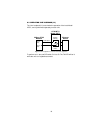
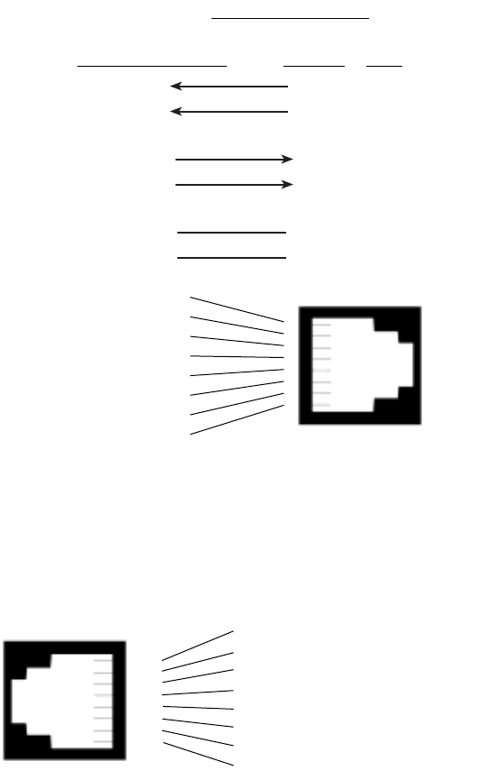
Connecting the 10Base-T Ethernet port to a PC (DTE)
To connect the Model 2707/I to another DTE device such as a 10Base-T
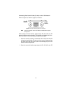
network interface card, construct a 10Base-T crossover cable and con-
nect the wires as shown in Figure 7 below and Figure 8 on page 15.
Figure 7.
Connecting the 10Base-T Ethernet Port to a PC
(No Connection) 8
(No Connection) 7
(No Connection) 6
(TX+) 5
(TX-) 4
(No Connection) 3
(RX-) 2
(RX+) 1
8
7
6
5
4
3
2
1
G.703
NETWORK SIGNAL
2707/I
SIGNAL PIN#
RX+
RX-
TX+
TX-
Shield
Shield
5
4
1
2
3
6
TX+
TX-
RX+
RX-
Shield
Shield
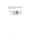
RJ-45 Cable (8-W
ire)
1 TD+ (data output from 2707/I)
2 TD- (data output from 2707/I)
3 RD+ (data input to 2707/I)
4 (no connection)
5 (no connection)
6 RD- (data input to 2707/I)
7 (no connection)
8 (no connection)
1
2
3
4
5
6
7
8