


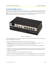


SmartNode 4630 overview 16
SmartNode 4630 Getting Started Guide 1 • General information
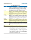
BRI 0/1
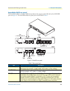
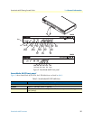
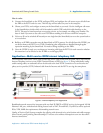
ISDN BRI NT/TE port, RJ-45 socket S0 (S/T) interface (see figure 2), connects the
SmartNode with an ISDN device over an S/T bus, e.g. a PBX or an NT. The inter-
face may be used as fallback if connected to an NT. The port can be switched
between TE and NT mode.The interface is internally terminated with 100 Ohm.
Point-to-point or point-to-multipoint configurable. If the port is in NT mode a phantom
power supply can be switched on to supply connected phones with power.
BRI 0/2
ISDN BRI NT/TE port, RJ-45 socket S0 (S/T) interface (see figure 2), connects the
SmartNode with an ISDN device over an S/T bus, e.g. a PBX or an NT. The port
can be switched between TE and NT mode.The interface is internally terminated
with 100 Ohm. Point-to-point or point-to-multipoint configurable. If the port is in NT
mode a phantom power supply can be switched on to supply connected phones
with power.
BRI 0/3
(SN4638 only)
ISDN BRI NT/TE port, RJ-45 socket S0 (S/T) interface (see figure 2), connects the
SmartNode with an ISDN device over an S/T bus, e.g. a PBX or an NT. The port
can be switched between TE and NT mode.The interface is internally terminated
with 100 Ohm. Point-to-point or point-to-multipoint configurable. If the port is in NT
mode a phantom power supply can be switched on to supply connected phones
with power.
BRI 0/4
(SN4638 only)
ISDN BRI NT/TE port, RJ-45 socket S0 (S/T) interface (see figure 2), connects the
SmartNode with an ISDN device over an S/T bus, e.g. a PBX or an NT. The port
can be switched between TE and NT mode.The interface is internally terminated
with 100 Ohm. Point-to-point or point-to-multipoint configurable. If the port is in NT
mode a phantom power supply can be switched on to supply connected phones
with power.
Console
Used for service and maintenance, the Console port (see figure 2), an RS-232 RJ-45
connector, connects the product to a serial terminal such as a PC or ASCII terminal
(also called a dumb terminal). (9600 bps, 8 bits, no parity, 1 stop bit, no flow con-
trol).
100-240 VAC 50-
60 Hz
Electricity supply socket for mains power cable. (see figure 2).
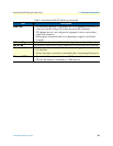
Reset
The reset button (see figure 2) has three functions:
• Restart the unit with the current startup configuration—Press (for less than 1 second)
and release the
Reset
button to restart the unit with the current startup configuration.
• Restart the unit with factory default configuration—Press the
Reset
button for
5 seconds until the
Power
LED (see figure 3 on page 17) starts blinking to restart
the unit with factory default configuration.
• Restart the unit in bootloader mode (to be used only by trained SmartNode tech-
nicians)—Starting with the unit powered off, press and hold the
Reset
button as
you apply power to the unit. Release the
Reset
button when the
Power
LED starts
blinking so the unit will enter bootloader mode.
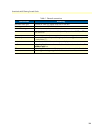
Table 2. Rear panel ports (Continued)
Port Description