


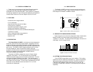
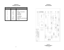

4.4.2 MULTIPOINT TWISTED PAIR CONNECTION
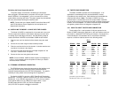
The Model 1012ARC supports multipoint applications using a star
topology. Maximum distance between the units will vary based upon
the number of drops, data rate, wire gauge, etc. Call Patton Technical
Support for specific distance estimates. Figure 6 shows how to wire
the cables properly for a Model 1012ARC star topology. Note that the
ground connection is not needed.
11
5.0 OPERATION
Once you have configured each Model 1012ARC and connected
the cables, you are ready to operate the units. Section 5.0 describes
the LED status monitors and the power-up procedure.
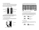
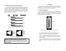
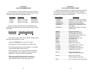
5.1 LED STATUS MONITORS
The Model 1012ARC features thirteen front panel status LEDs that
indicate the condition of the modem and communication link. Figure 8
shows the relative front panel positions of the LEDs. Following Figure
8 is a description of each LED’s function.
• The “PWR” LED glows when power is being applied to the
modem card through its mid-plane chassis connection.
• The “TD” and “RD” indicators glow green to show a positive
voltage on the interface, and glow red to show negative voltage or
an idle data state.
• The “CD” indicators glow green to show a positive voltage on the
interface, and glow red to show negative voltage or an idle data
state.
12
HOST FIRST SLAVE SECOND SLAVE
XMT+ RCV+
RCV+
XMT- RCV-
RCV-
RCV+ XMT+
XMT+
RCV- XMT-
XMT-
Figure 6. Star wiring for Model 1012ARC host and slaves
1 - Blue
2 - Orange
3 - Black
4 - Red
5 - Green
6 - Yellow
7 - Brown
8 - Slate
1 - Blue
2 - Yellow
3 - Green
4 - Red
5 - Black
6 - White
Figure 7. AT&T standard modular color codes
Notice! Any modular twisted pair cable connected to the
Model 1012ARC must be shielded cable, and the outer shield
must be properly terminated to a shielded modular plug on both
ends of the cable.
Figure 8. The Model 1012ARC front panel, showing LED positions
Model 1012ARC
Power
TD
RD
CD
TD
RD
CD
Unit
A
Unit
B
Channel A
Channel B