10 of 11
ISSUED: 1-11-08 SHEET #: 055-9495-2 10-16-08
Visit the Peerless Web Site at www.peerlessmounts.com
For customer care call 1-800-865-2112 or 708-865-8870.
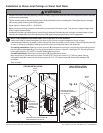
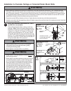
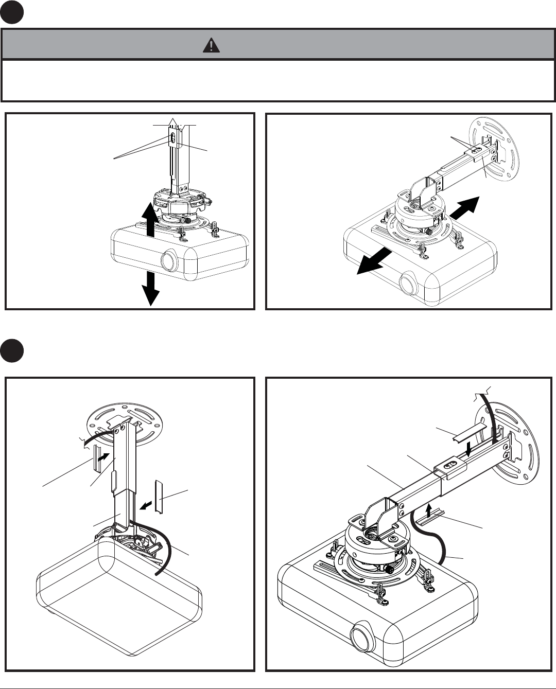
Cut cable covers (Q) to the length of inner channel (C) and outer channel (B) openings, leaving space for cables if
routed through channels. Snap cable covers (Q) into openings as shown.
8
CABLES
CUT TO
LENGTH OF
OPENING
Q
CUT TO
LENGTH OF
OPENING
Q
CABLES
CEILING INSTALLATION
WALL INSTALLATION
(EXCEPT FOR EXC MODELS)
CUT TO
LENGTH OF
OPENING
Q
CUT TO
LENGTH OF
OPENING
Q
B
C
B
C
7
CEILING INSTALLATION
WALL INSTALLATION
(EXCEPT FOR EXC MODELS)
D
D
Install Cable Covers
Adjusting Mount Extension
• On ceiling installations, clamp plate adjustment screws support weight of projector when fully tightened. Weight of the
projector will need to be supported if clamp plate screws are loosened.
WARNING
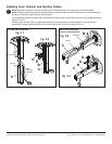
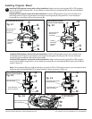
While supporting the weight of the projector, loosen clamp plate screws half a turn and position projector to the
desired extended position. Retighten clamp plate screws securely.
CLAMP PLATE
SCREWS
CLAMP PLATE
SCREWS


