2 Pelco Manual C1421M-B (8/98)
1.2 RECOMMENDED TOOLS Pelco does not supply basic tools needed for the installation process. The following
tools are recommended:
Phillips screwdriver
Flat screwdriver
2.0 DESCRIPTION The WD35 Series Defroster Kits are continuous duty defroster kits for use with the
EH3500 Series Enclosures.
2.1 MODELS WD35-1 Window defroster kit, 120 VAC, 3 watts
WD35-2 Window defroster kit, 24 VAC, 3 watts
WD35-3 Window defroster kit, 230 VAC, 3 watts
2.2 CERTIFICATIONS The products identified below have been tested and certified for agency compli-
ance as noted.
Agency Complance Certification
Model CE FCC UL CSA/cUL
WD35-2 X
WD35-3 X
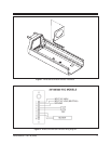
3.0 INSTALLATION To install the WD35 Series Window Defroster Kit, perform the following steps (see
Figure 1):
1. Disconnect the enclosure from all sources of power and open the enclosure
lid.
2. Remove the camera and sled.
3. Loosen the screws in the bottom window bracket.
4. Remove the top window bracket.
5. Position the window defroster with the metal plate against the inside face of
the window. Make sure the defroster wires are in the lower left corner of the
window.
6. Reinstall the top window bracket.
7. Tighten the bottom window bracket screws.
8. Route the defroster wires between the track rail and the body of the enclosure.
Attach the window defroster wires to the PCB terminal locations as shown in
Figure 2. Make sure the window defroster wires are not obstructing any other
accessories within the enclosure.
9. Reinstall the camera and sled.
10. Close the enclosure lid and reconnect power to the enclosure.
NOTE:
Window defrosters manu-
factured after July 1998 have a
metal plate affixed to the defroster.
NOTE:
When a window defroster
and blower are both used, the two
accessories will share the same
terminal locations on the PCB.


