PHYSICAL INSTALLATION CM9760-SAT 1-3
3.0 ADDITIONAL SAT CONNECTIONS
If you want to operate and program from the local SAT SIDE of a
system configuration, a number of additional devices and connections
remain to be made. In order to view the results of local operations and
program SAT menus, a local monitor is needed.
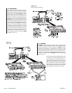
3.1 LOCAL MONITOR
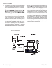
The local Monitor is used to display link camera call-ups and
switcher functions for local SAT operations. It is also used to
display the main program menu and its sub-menus during SAT
programming and setup. To install the local monitor:
1. Install the monitor.
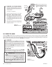
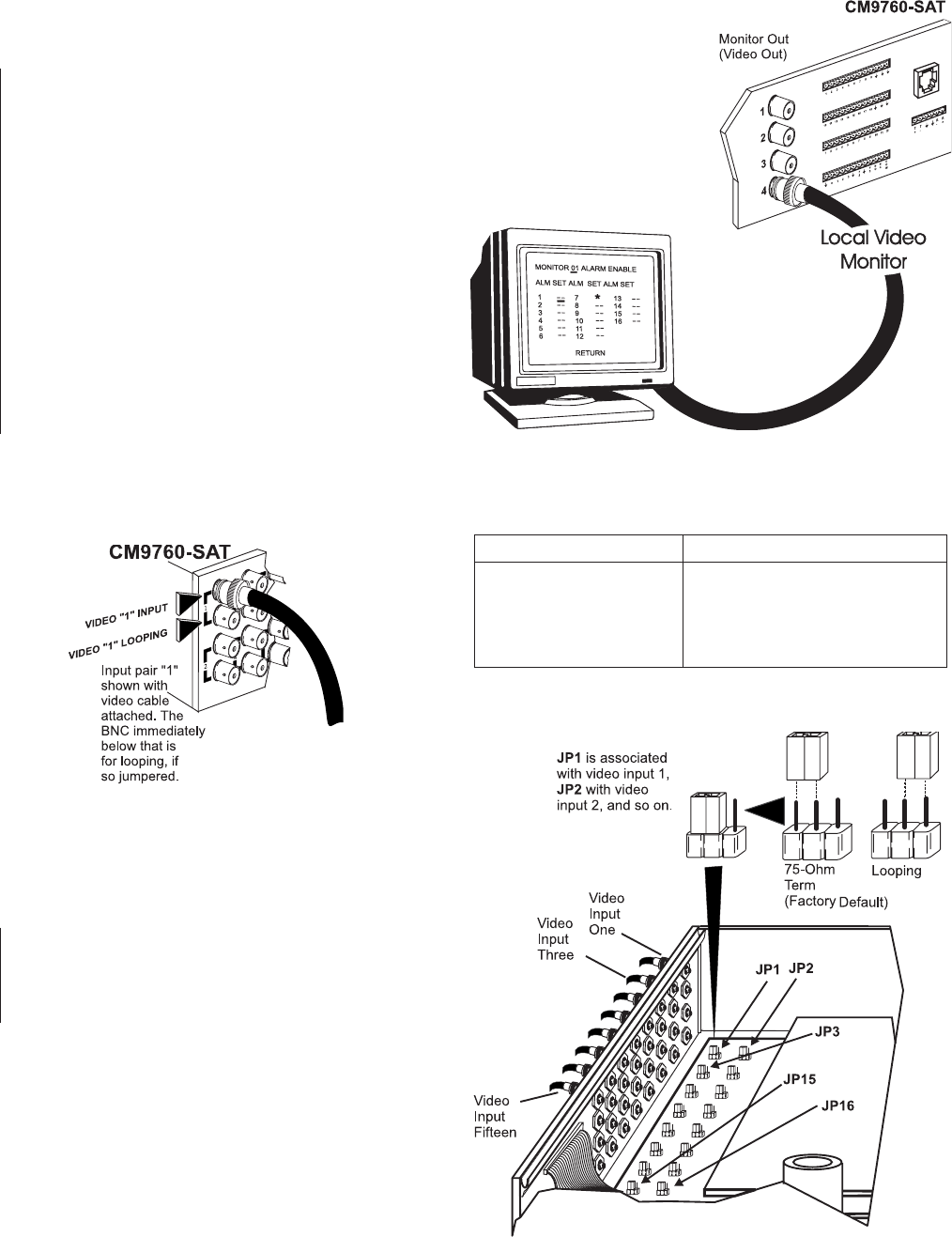
2. Run a video output from the SAT to the installed monitor.
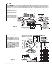
3.2 LINK OR SATELLITE CAMERAS
(VIDEO INPUTS)
The CM9760-SAT can accommodate 16 video inputs that are
individually jumper-selectable for terminated or looping opera-
tion. All video inputs are set to 75-ohm termination at the factory.
See Table A for typical coaxial video cable and recommended
distances. Use only coaxial cable specified for CCTV systems.
Run the video cables from the cameras or camera receivers to
the selected video inputs on the rear of the CM9760-SAT (the top
connector for each input pair).
Table A
Video Coaxial Cable Requirements
Cable Type Maximum Distance
RG-59U 750 ft. (228.6 m)
RG-6/U 1,000 ft. (304.8 m)
RG-11/U 1,500 ft. (457.2 m)
Consult factory Above 1,500 ft (457.2 m)
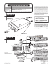
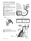
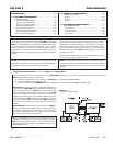
Figure 1-7
Loop-through Configuration
Local SAT operation and control
functions are displayed here,
including the menus for SAT
programming. You should have
at least one local display available
to monitor local operations.
Depending on your application,
you can have up to three monitor-outs
configured for local use. Monitor functions
are chosen during programming
(see Section 2, Monitor Programming
Menu–page 2 of 3).
NOTE: If all monitor-outs
are set up as tie lines, SAT
menu programming is done
from the 9760-KBD.
3.2.1 Looping Video Inputs
As stated at the beginning of this manual, the loop-thru option is avail-
able for each video input. If you want this option for any input, remove
the top cover of the unit and reposition the jumpers according to the
information provided in Figure 1-7.
Figure 1-5
Local SAT Monitor
Figure 1-6
Link (Satellite) Camera Inputs


