1-4 C1510M-A (2/03) SECTION 1
3.3 RECEIVERS
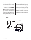
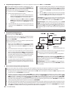
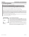
If any camera you want to install is PTZ cap-
able, then the receiver for that camera must be
individually wired for power and control (depen-
dent on type). The CM9760-SAT has built-in
software that is individually selectable for each
camera control type. The correct protocol is se-
lected via menu choices when programming the
Cameras menu for each individual input (see
Section 2,
Camera Programming Menu-Page
2 of 2
). Allowed camera control types must be
able to utilize one of two communication proto-
cols for connection to the SAT. One control type
is Coaxitron
®
. Coaxitron (standard or extended)
receivers utilize the input video line as a path
for sending control commands to the receiver.
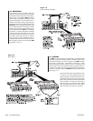
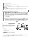
The other control type is RS-422 “P” protocol
receivers that are wired independent of the
video path. RS-422 command control connec-
tions originate at COM 1 on the rear of the SAT
(see Figures 1 and 1-8).
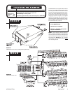
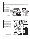
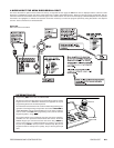
Figure 1-9
Alarm Wiring
3.4 ALARMS
The SAT has 16 alarm inputs, each designed for use with standard
single-pole, single-throw (SPST) switches. The alarm inputs on the
connector correspond, on a one-to-one basis, to the SAT’s 16 video
inputs; that is, video input 1 corresponds to alarm input 1, video
input 2 corresponds to alarm input 2, and so on. To properly recall
alarmed video, each alarm connection must correspond to the cor-
rect video input. Each must also be appropriately programmed for a
number of variables. Refer to Section 2,
Alarm Programming
Menu-Page 1 of 1.
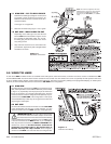
Connect the alarm inputs as illustrated in Figure
1-9. Alarms 1-9 use the indicated 12-pin con-
nector (provided). For each alarm-video pair in-
stalled and accounted for, wire a return ground
path. Utilize a ground connection located on the
same connector on which your alarm input is
wired. Proceed on a pair-by-pair basis until all
video-associated alarm pairs are wired. Utilize
both alarm wiring connectors, if necessary.
Figure 1-8
Receiver Wiring and Control


