MATRIX SYSTEM
CARD CAGE
REMOTE KEYBOARD
DATA CABLE
SUPPLIED WITH
KEYBOARD
DATA CABLE
SUPPLIED WITH
UPS
CM9505UPS
USER SUPPLIED
4-CONDUCTOR
DATA CABLE SUPPLIED
WITH JUNCTION BOX
CM9505J
JUNCTION BOX
MATRIX SYSTEM
CARD CAGE
REMOTE KEYBOARD
DATA CABLE
SUPPLIED WITH
KEYBOARD
USER SUPPLIED
8-CONDUCTOR
DATA CABLE SUPPLIED
WITH JUNCTION BOX
CM9505J
JUNCTION BOX
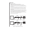
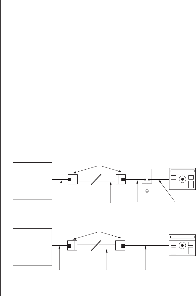
Figure 1. CM9505UPS/CM9505J Configuration
INSTALLATION
The following parts are supplied:
2 CM9505J Junction Boxes with 25-foot (7.6 m) data cable, or
1 CM9505UPS Series Universal Power Supply with 25-foot (7.6 m) data cable
1. Connect either a four-conductor or eight-conductor cable (not supplied) between the
junction boxes, depending on whether you will install a CM9505UPS Series power supply
(refer to Figure 1).
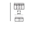
Refer to Table A for the wiring assignments and to Figure 2 for the terminal locations. If
you are using a four-conductor cable, connect the wires to terminals 1, 2, 7, and 8 only.
Refer to Table B for the maximum cable distances if you use an eight-conductor cable
between the junction boxes. The maximum length is limited by the distance restrictions of
the DC power lines.
If you use a four-conductor cable and the CM9505UPS power supply, the maximum cable
distance between the junction boxes is 2,000 feet (610 m). For distances over 2,000 feet
(610 m), the CM9595UPS-422 power supply with data repeater is recommended.
2. Connect the 25-foot (7.6 m) cables (supplied) between the junction boxes, power supply,
and matrix system card cage as applicable (refer to Figure 1).
3. Plug the power supply into the wall outlet.


