


C2647M (10/06) 13
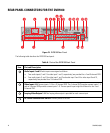
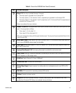
Relays 1–2: One relay is provided for every 4 channels:
• One relay output is provided for a 4-channel DVR.
• Two relay outputs (1, 2 for channels 1 and 2, respectively) are provided for an 8-channel DVR.
• Four relay outputs (1, 2 for channels 1 and 2, respectively and 3, 4 for channel 9 and 10, respectively) are
provided for a16-channel DVR.
Relays are numbered from top to bottom.
Alarms 1–4 and 5–8: One programmable alarm input is provided for each video input. Alarm inputs for video
input 1–8 are organized as follows:
• Alarm input 1–4 is for video 1–4
• Alarm input 5–8 for video input 5–8
Alarms are numberd from the top left through the bottom right. The rear panel layout might be different for the
4 and 8 channel DVR.
Audio Inputs 3 and 4: Audio inputs 3 and 4 are for channel 9 and 10. For information about audio inputs for a
4 or 8 channel DVR5100, refer to item 3 in this table.
Video Inputs 9–16: Camera inputs 9–16 for a 16 channel DVR. The rear panel layout might be different for
the 4 and 8 channel DVR.
Looping Video Outputs 9–16: One looping video output is provided for each camera input.
USB 2.0 Ports: Two USB 2.0 ports are provided for connecting an USB device, such as an optional KBD5000,
USB PC keyboard, or USB storage media.
RJ-45 Port: Gigabit Ethernet RJ-45 port (1000BaseT).
3.5 mm Audio Jack: Provides mono audio output.
Analog Video Output: Output connector, for sending video to an analog device such as an NTSC or PAL
monitor.
DB15 VGA: VGA connector for connecting a primary VGA monitor.
S-Video: Connects a primary monitor.
Relays 3–4: One relay is provided for every 4 channels. Relay output 3 and 4 for channel 9 and 10 are
provided for a16-channel DVR. Relays are numbered from top to bottom.
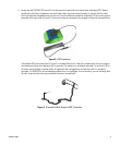
Table A. Parts of the DVR5100 Back Panel (Continued)
Item Part and Description