


Pelco Manual C551M (4/98) 11
4.0 OPERATION
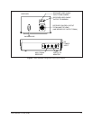
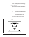
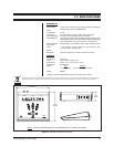
In general, all operating controls on the KBD9000 are self-explanatory. See Section
4.2, KBD9000 CONTROLS, for more information about each control function.
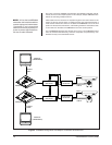
4.1 FUNCTIONAL CIRCUIT DESCRIPTION
The basic functional concept of a Coaxitron
®
system feeds 15 control pulses in a re-
verse direction from the KBD9000 control transmitter to the receiver located near each
camera station. These control pulses do not interfere with the video monitor presenta-
tion because they occur during the vertical blanking interval of the video signal.
Coaxial cable impedance matching is assured by the video amplifier in the control
receiver. Proper receiving and termination impedance is likewise assured by the
terminating resistor in the KBD9000 control transmitter. Any equipment placed be-
tween the remote and local locations must be of the “loop-through” or “bridging”
type; line amplifiers cannot be tolerated.
Response time of the system is normally less than 30 ms. Error detection circuitry
is incorporated to immunize the system from externally generated noise. Under
extremely adverse environmental noise conditions response time may increase and
control functions can fail. Under such extreme conditions, however, provision is
made to inhibit all momentary functions.
The proper function of the Coaxitron
®
system depends on the compatibility of two
signals simultaneously traveling in opposite directions in the same coaxial cable. If
the control signal is made large, compared to the video signal, there is the risk that
associated equipment will be adversely affected. If the control signal is made small,
compared to the video signal, it becomes difficult to separate it from the video
signal (and any incumbent noise or hum). Therefore, the Coaxitron
®
system is de-
signed to function with video and control signals nominally equal.
Under such circumstances, reliable performance can be predicted with cable lengths
up to 1,500 feet (457 m). Beyond this distance, the control signal amplitude can
become attenuated sufficiently to make performance marginal. Marginal performance
is also approached if the video signal is allowed to become excessive — the dy-
namic range of the receiver video amplifier is one limitation. Sending end distortion,
produced by the coaxial cable, is typically the major contributor to the malfunction-
ing of a Coaxitron
®
system. The amplitude of distortion products is proportional to
video signal amplitude and is a nonlinear function of cable length. The influence of
these distortion products upon system performance is difficult to predict if signal
amplitude is allowed to exceed specifications.
Normally, auto-iris functions will maintain a video level well within reasonable limits
and assure reliable performance. Often, however, automatic or manual level settings
may be made abnormally high (perhaps to compensate for long cable losses or to
produce a picture with more contrast). An excessively high video level setting can
cause the Coaxitron
®
control system to fail completely — with all control functions
disabled. In order to prevent system failures due to excessively high video levels, it
is recommended that cameras be powered by the receiver.
The KBD9000 is designed to combat prolonged loss of control due to the condi-
tions described previously by providing the following protective functions:
1. Simultaneous commands from two different sources are processed to assure
that manual iris control cannot be inadvertently selected in place of automatic
control.
2. A sustained (20 to 40 second) illegal command condition results in (a) camera
off, (b) automatic iris, or (c) manual pan.
These functions greatly reduce the possibility of loss of control and usually elimi-
nate the need for service.