


Pelco Manual C820M-D (1/01) 5
INSTALLATION
1. Place the unit on a flat surface, or install it in an equipment rack using the appropriate
rack-mount kit.
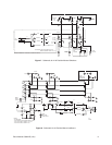
2. Refer to Figures 1 - 6 and select the desired configuration for your installation. Make
all equipment connections as illustrated in the drawings. Refer to Table A for the type
of coaxial cable to use.
3. Plug in the power cord. The switcher will begin operating.
NOTE:
For the maximum
recommended cable dis-
tances refer to the installa-
tion manuals supplied with
equipment (camera, lens
and monitor) to be used with
the switcher.
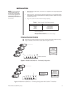
TERMINATING SWITCHERS
When using non-looping switchers, the monitor should be terminated unless the looping
output, if available, on the monitor is used. (Refer to Figures 1 and 2.)
Table A. Video Coaxial Cable Requirements
Cable Type* Maximum Distance
RG59/U 750 ft (229 m)
RG6/U 1,000 ft (305 m)
RG11/U 1,500 ft (457 m)
* Minimum cable requirements:
75 ohms impedance
All-copper center conductor
All-copper braided shield with 95% braid coverage
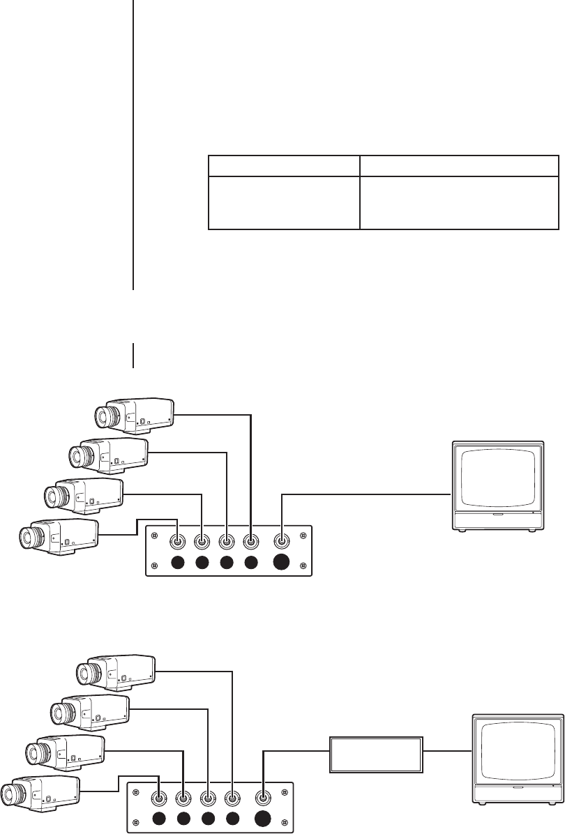
Figure 1. MS500 Series Switchers - Terminating Configuration
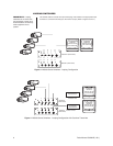
Figure 2. MS500 Series Switchers - Terminating Configuration with Coaxitron
®
Transmitter
CAMERA
MON
4321
AC INPUT
MS504DT (REAR VIEW)
TERMINATE
MONITOR
(SWITCH IN THE
75Ω POSITION)
MS504AF (REAR VIEW)
CAMERA
MON
4321
AC INPUT
COAXITRON
TRANSMITTER
TERMINATE
MONITOR
(SWITCH IN THE
75Ω POSITION)
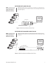
TERMINATE LOOPING
OUTPUT AT 75Ω