


[ 4 ] Pelco Manual C1991M-C (9/04)
INSTALLATION
The monitor may be placed on any flat surface (desk or table) or rack-mounted. To rack-mount the
monitor follow the instructions supplied with the rack mount kit.
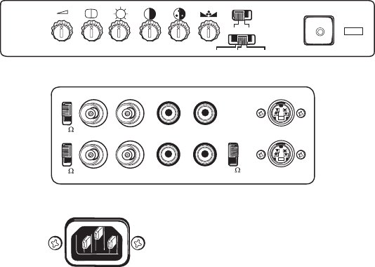
Video and Power Connections
1. Video Cable Connection (Refer to Table A for video coaxial cable requirements.)
a. Connect the video cable to the BNC video input labeled V1 IN on the back panel of the monitor.
If the installation requires a second video input, connect a video cable to the BNC video input la-
beled V2 IN.
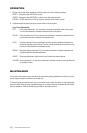
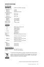
b. Looping Operation Only - Connect a video cable to the BNC connector labeled V1 OUT. If the in-
stallation requires a second video output, connect a video cable to the BNC video output labeled
V2 OUT. Refer to Figures 2 and 3.
2. Impedance Switch Setting
a. Terminating Operation Only - Set the termination switch to 75Ω position.
b. Looping Operation Only - Set the impedance switch to the V1-HI and V2-HI positions. Refer to
Figures 2 and 3.
3. Plug the power cord (provided) into the AC INLET connection on the back panel. Plug the other end
of the cord into a power receptacle.
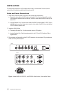
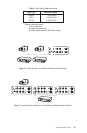
Figure 1. Models PMCS15A, PMCS17A, and PMCS19A Color Monitors, Front and Back Panels
V2-H I
V1 OUT
V1 IN AU1 IN
AU1 OUT
Y/C-HI
S-VIDEO IN
S-VIDEO OUT
V2 OUT
V2 IN
AU2 IN
AU2 OUT
V1-H I
VOLUME SHARP BRIGHT CONT . COLOR TINT
VIDEO 1 VIDEO 2 S-VIDEO
AU1 AU2
FRONT
BAC K
AC INLET
75
75
75