4 C831M-F (10/04)
Installation
The VS5104/VS5108 switcher is designed for either looping or terminating operation. The unit is shipped ready for terminating operation, but it
can be modified for looping operation. Looping and terminating inputs may be mixed.
1. To install the VS5104/VS5108, do the following:
a. Terminating Operation - Proceed to step 2.
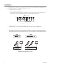
b. Looping Operation - To convert to looping operation, remove the cover. Locate the 75-ohm resistors at the rear of the BNC jacks. Use wire
cutters to clip one of the resistor leads for each input that you want to loop. Refer to Figure 1. Replace the cover.
Figure 1.
Rear Panel Internal View
2. Make all equipment connections for your system configuration. Refer to Figure 2.
3. Connect the AC adapter to the 12 VAC input socket on the switcher. Connect the transformer to a 120 or 230 VAC power supply.
4. Set all channel switches to the AUTO (center). If a video input is not connected, set the corresponding channel switch to the BYPASS (down)
position.
5. Adjust the DWELL interval control with a screwdriver to the desired switching interval, 1 to 70 seconds nominal. Rotate the control clockwise for
longer intervals and counter-clockwise for shorter intervals. This control is a 15-turn precision potentiometer. The approximate ratio is one full turn
per 4–5 seconds of delay.
Figure 2.
VS5104/VS5108 System Configuration
75-OHM RESISTOR
BNC CONNECTOR
CLIP
HERE
12 VAC
INPUT
12 VAC
INPUT
MON
OUT
MON
OUT
MONITOR
AUTO
BYPASS
MONITOR
AUTO
BYPASS
VS5104 VIDEO SWITCHER
DWELL
1234
VS5108 VIDEO SWITCHER
1234
DWELL
5678
VS5104
FRONT VIEW
BACK VIEW
FRONT VIEW
BACK VIEW
VS5108