


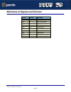

Host Card Back Panel Connectors and Pinouts
Page 36
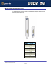
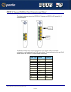
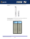
SPEED LE Express RJ45 Back Panel Connectors and Pinout
The following diagram shows the SPEED2 LE Express and SPEED4 LE Express RJ-45
cards back panel.
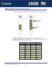
The RJ45 connector has a 10-pin configuration. If you require an 8-pin connector
configuration, use the pinouts in the RJ45 8-pin column. The connector pinout for each RJ45
socket fitted to the SPEED LE Express cards is as follows;
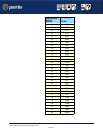
RJ45 10-pin EIA-232 RJ45 8-pin
1 RI N/A
2 DCD 1
3 RTS 2
4 DSR 3
5 TXD 4
6 RXD 5
7 S-GND 6
8 CTS 7
9 DTR 8
10 N/A
Shell C-GND Shell