


2-4
RPS Series: Remote Power Switches - User's Guide
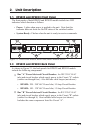
As shown in Figure 2.2, RPS1620 and RPS1630 units include the following
components:
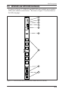
Manual Switch Button: A Manual Control Button for the unit’s
switched plugs. To manually switch plugs "On" or "Off", press and
hold the control button for approximately three seconds. If desired, the
Manual Switch Button can also be disabled (Section 5.3.1.)
Note: When the Manual Switch Button is used, Boot / Sequence
Delay Times will be applied as described in Section 5.3.3.2.
Ready Indicator: Flashes when ready to receive commands.
Activity Indicator: Flashes to indicate activity at the Network Port.
10Base-T (Network) Port: An RJ45 Ethernet Port for connection to
your TCP/IP network. The default IP Address is 192.168.168.168, for
more information, please refer to Section 5.3.4.
RS232 Console Port: A DB9, RS232 serial port (DTE), for connection
to a local terminal or external modem, as described in Section 4.3.
Master Power Switch: This switch must be "On" in order for the RPS
to function. Note that this switch is not used to set the On/Off status of
the switched outlets.
Switched Plugs and Plug Indicators:
• Model RPS1620: Sixteen (16) 208 to 240 VAC outlets, split into
two separate power circuits. Each power circuit can switch a total
load of up to 10 Amps. Circuit "A" includes plugs 1 through 8, and
Circuit "B" includes plugs 9 through 16.
• Model RPS1630: Sixteen (16) 100 to 120 VAC outlets, split into
two separate power circuits. Each power circuit can switch a total
load of up to 15 Amps. Circuit "A" includes plugs 1 through 8, and
Circuit "B" includes plugs 9 through 16.