


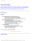
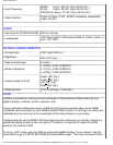

Product Information
3
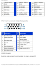
T.M.D.S. Data2/4
Shield
11
T.M.D.S. Data1/3
Shield
19
T.M.D.S. Data0/5
Shield
4
No connect
12
No connect 20 No connect
5
No connect
13
No connect 21 No connect
6
DDC Clock
14
+5V Power 22
T.M.D.S. Clock
Shield
7
DDC Data
15
Hot Plug Detect 23 T.M.D.S. Clock+
8
No connect 16 Ground (for +5V) 24 T.M.D.S. Clock-
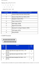
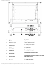
2. The 15-pin D-sub connector (male) of the signal cable:
Pin
No.
Assignment
Pin
No.
Assignment
1
Red video input
9
DDC +5V
2
Green video input
10
Cable detect
3
Blue video input
11
Identical output,
connected to pin 10
4
Ground
12
Serial data line (SDA)
5
NC
13
H. Sync / H+V
6
Red video ground
14
V. Sync
7
Green video ground
15
Data clock line (SCL)
8
Blue video ground
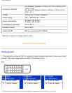
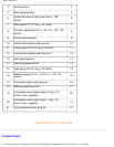
3. RS232 Connector
D-sub 9-pin male connector for communication with plasma engine or PC.
file:///D|/My%20Documents/dfu/BDL3221V/english/320wn6/PRODUCT/PRODUCT.HTM (7 of 10)2005-11-07 12:47:57 PM