


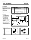

Philips Semiconductors Product specification
TOPFET high side switch BUK214-50Y
SMD version of BUK209-50Y
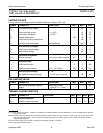
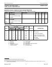
OVERLOAD PROTECTION CHARACTERISTICS
5.5 V ≤ V
BG
≤ 35 V, limits are at -40˚C ≤ T
mb
≤ 150˚C and typicals at T
mb
= 25 ˚C unless otherwise stated.
Refer to
TRUTH TABLE.
SYMBOL PARAMETER CONDITIONS MIN. TYP. MAX. UNIT
Overload protection V
BL
= V
BG
I
L(lim)
Load current limiting V
BG
≥ 9 V 20 30 40 A
Short circuit load protection
V
BL(TO)
Battery load threshold voltage
1
V
BG
= 16 V 8 10 12 V
V
BG
= 35 V 15 20 25 V
t
d sc
Response time
2
V
BL
> V
BL(TO)
- 180 250 µs
Overtemperature protection
T
j(TO)
Threshold junction 150 170 190 ˚C
temperature
3
∆T
j(TO)
Hysteresis - 10 - ˚C
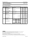
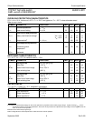
SWITCHING CHARACTERISTICS
T
mb
= 25 ˚C, V
BG
= 13 V, for resistive load R
L
= 13 Ω.
SYMBOL PARAMETER CONDITIONS MIN. TYP. MAX. UNIT
During turn-on from input going high
t
d on
Delay time to 10% V
L
-4570µs
dV/dt
on
Rate of rise of load voltage 30% to 70% V
L
- 0.4 1.0 V/µs
t
on
Total switching time to 90% V
L
- 110 180 µs
During turn-off from input going low
t
d off
Delay time to 90% V
L
-5080µs
dV/dt
off
Rate of fall of load voltage 70% to 30% V
L
- 0.7 1.1 V/µs
t
off
Total switching time to 10% V
L
- 75 120 µs
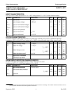
CAPACITANCES
T
mb
= 25 ˚C; f = 1 MHz; V
IG
= 0 V. designed in parameters.
SYMBOL PARAMETER CONDITIONS MIN. TYP. MAX. UNIT
C
ig
Input capacitance V
BG
= 13 V - 15 20 pF
C
bl
Output capacitance V
BL
= 13 V - 200 300 pF
C
sg
Status capacitance V
SG
= 5 V - 11 15 pF
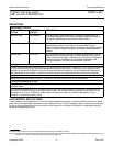
1 The battery to load threshold voltage for short circuit protection is proportional to the battery supply voltage. A graph showing V
BL(TO)
versus
V
BG
will be provided in the product specification. After short circuit protection has operated, the input voltage must be toggled low for the
switch to resume normal operation.
2 Measured from when the input goes high.
3 After cooling below the reset temperature the switch will resume normal operation.
September 2002 6 Rev 2.000