


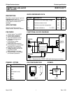

Philips Semiconductors Product specification
TOPFET high side switch BUK216-50YT
SMD version
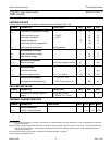
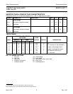
OVERLOAD PROTECTION / DETECTION CHARACTERISTICS
6 V ≤ V
BG
≤ 35 V, limits are at -40˚C ≤ T
mb
≤ 150˚C and typicals at T
mb
= 25 ˚C unless otherwise stated.
Refer to
TRUTH TABLE.
SYMBOL PARAMETER CONDITIONS MIN. TYP. MAX. UNIT
Overload protection V
BL
= V
BG
I
L(lim)
Load current limiting V
BG
≥ 9 V 10 15 21 A
Short circuit load detection Status indication only
V
BL(TO)
Battery load threshold voltage
1
V
BG
= 16 V 8 10 12 V
V
BG
= 35 V 15 20 25 V
Overtemperature protection
T
j(TO)
Threshold junction 150 170 190 ˚C
temperature
2
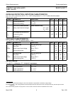
SWITCHING CHARACTERISTICS
T
mb
= 25 ˚C, V
BG
= 13 V, for resistive load R
L
= 13 Ω.
SYMBOL PARAMETER CONDITIONS MIN. TYP. MAX. UNIT
During turn-on from input going high
t
d on
Delay time to 10% V
L
-4060µs
dV/dt
on
Rate of rise of load voltage 30% to 70% V
L
- 0.5 1 V/µs
t
on
Total switching time to 90% V
L
- 160 225 µs
During turn-off
3
from input going low
t
d off
Delay time to 90% V
L
- 70 100 µs
dV/dt
off
Rate of fall of load voltage 70% to 30% V
L
- 0.5 1 V/µs
t
off
Total switching time to 10% V
L
- 95 130 µs
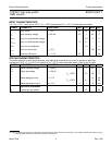
CAPACITANCES
T
mb
= 25 ˚C; f = 1 MHz; V
IG
= 0 V. designed in parameters.
SYMBOL PARAMETER CONDITIONS MIN. TYP. MAX. UNIT
C
ig
Input capacitance V
BG
= 13 V - 15 20 pF
C
bl
Output capacitance V
BL
= 13 V - 425 600 pF
C
sg
Status capacitance V
SG
= 5 V - 11 15 pF
1 The battery to load threshold voltage for short circuit detection is proportional to the battery supply voltage.
2 Latched protection. After cooling below the threshold temperature the switch will resume normal operation only after the input has been
toggled low.
3 For measurement purposes an Input pulse of 1.5ms is used to ensure the device is stabilised in the on state.
March 2002 6 Rev 1.200