


SmartPanel Projector Driver Application Note
Panasonic PT-LB10VU
© 2005 SP Controls Inc. 601 Minnesota Suite 115, San Francisco, CA 94107
help@spcontrols.com
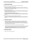
II. CONTROL WIRING
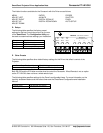
34 5
8
76
21
PROJECTOR CONTROL
RS232 IR/SERIAL
RX
GND
CTS
RTS
TX
+12V
GND
IR/SER
SENSE
RS-232 to RS-232C
IR Emitter
(included with Panel)
1/8" Mini
Female
Male Mini-DIN
RX to Pin 5
TX to Pin 3
GND to Pin 4
RS-232 to
SERIAL
IR Emitter to
any IR window
This section specifies wiring for the Panasonic projector.
Note: The Panasonic PT-LB10VU projector serial port is a
female 8-pin mini-DIN. This document provides instructions
for terminating the RS-232 control cable directly onto a
male 8-pin mini-DIN connector. If you wish to terminate the
control cable on a standard DB9 connector, an adaptor
cable may be separately ordered from Panasonic
(Panasonic part no. ET-ADSER).
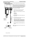
A. RS-232 should be connected to the port labeled
SERIAL. Connection should be as follows:
1. Wire the Panel to a male Mini-DIN 8-pin connector as
follows:
Panel RX to 5
Panel TX to 3
Panel GND to 4
2. Connect the Mini-DIN to the Panasonic projector port
labeled SERIAL.
B. The IR Emitter should be connected to the one of the
Panasonic IR windows as follows:
1. Wire the Panel to a female 1/8” Mini as shown; wire
IR/SER to tip and GND to ring. Splicing and direct
wiring to the IR Emitter is not recommended as it
makes removal of the Panel for service more difficult.
2. Connect the included IR Emitter to the female mini.
3. Affix the IR Emitter to one of the IR windows on the
projector.
Note: The emitter glows red when IR is emitted so wiring
can be verified.