


OB-U0192
4
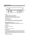
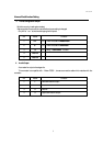
Rear Panel
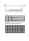
1 . DC Input
Pin
Name
Function
1
+12
Power supply input of DC +12V
2
G
Ground
3
G
Ground
4
+5
Power supply input of DC +5V
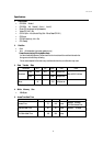
2 . ATAPI Interface
It should be connected with the Enhanced-IDE port of the computer. Use 40pin flat type cable.
Length of the cable is less than 18inchs(46cm) according to the ATA specifications.
It may cause data transfer error, if longer cable more than above value is used.
Pin
Name
Pin
Name
Pin
Name
Pin
Name
1
RESET-
11
DD3
21
DMARQ
31
INTRQ
2
GND
12
DD12
22
GND
32
IOCS16-
3
DD7
13
DD2
23
DIOW-
33
DA1
4
DD8
14
DD13
24
GND
34
PDIAG-
5
DD6
15
DD1
25
DIOR-
35
DA0
6
DD9
16
DD14
26
GND
36
DA2
7
DD5
17
DD0
27
IORDY
37
CS1FX-
8
DD10
18
DD15
28
CSEL
38
CS3FX-
9
DD4
19
GND
29
DMACK-
39
DASP-
10
DD11
20
(KEYPIN)
30
GND
40
GND
Remarks: The minus sign indicates active low.