


9
No.
1
2
3
4
5
6
7
8
9
0
-
=
~
!
@
#
$
%
^
&
*
(
)
_
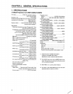
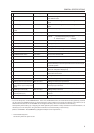
GENERAL SPECIFICATIONS
Function
Used for switching the control level of the ABL link control voltage
when ABL link is ON.
Input terminal of ABL signal, remote control signal and RS-232C
signal
Output terminal of ABL signal, remote control signal, and RS-232C
signal
Connected to adjusting remote control (optional)
RS-232C communication connector
Video input and Y/C input external switching control signal input
terminal Normal(video signal input) : Open
Select Y/C input : Low(0V)
Luminance signal input terminal
Color signal input terminal
Video signal input terminal
Video input terminal 9 through-out terminal
Turns on when terminates the video input terminal 9 at 75 ohm
Turns on when linked to ABL
Turns on when used on multi screen
Switches the color temperature. 1:Normal use. 2:Re-exposure
Switches VIDEO input, Y/C input, RGB input.
Switches VIDEO input and Y/C input with the external control signal
6 at VIDEO position
Power OFF : STANDBY (Red LED) lights up
Power ON : ON (Green LED) lights up
Accumulated duty time: * Switch which displays setting states of
each switch on the screen.
RGB signal input terminal
Switches RGB signal input terminal type
RGB signal vertical sync input terminal
RGB signal horizontal sync and composite sync (Only for input sig-
nal H/V sync) input terminal
RGB signal B input terminal
RGB signal G and composite sync (Input signal G on sync) input
terminal
RGB signal R input terminal
Type
Slide switch
DIN 6PIN
DIN 6PIN
Mini jack
D-sub 25 PIN (Female)
BNC connector
BNC connector
BNC connector
BNC connector
BNC connector
Slide switch
Tact switch
Tact switch
Tact switch
Tact switch
Tact switch
Tact switch
D-sub 9PIN (Male)
Slide switch
BNC connector
BNC connector
BNC connector
BNC connector
BNC connector
Name
ABL link switch
Linked input terminal
Linked output terminal
Remote control connection ter-
minal
RS-232C port
Control input terminal
Y (Luminance) input terminal
C (Color) input terminal
Video input terminal
Video output terminal
TERMINATE switch
COMBINATION switch
MULTI switch
COLOR MODE switch
INPUT switch
POWER switch
STATUS switch
RGB input terminal
RGB input select switch
RGB input terminal (Vertical sync)
RGB input terminal
(Horizontal sync/composite
sync)
RGB input terminal (B)
RGB input terminal
(G/composite sync)
RGB input terminal (R)
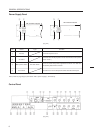
• To turn off the power, use the POWER switch - of the unit, the RS-232C control, or wired remote control (optional). (If turned
off using the main POWER switch or by disconnecting the power cable from the outlet, the settings of the above = to @
switches and the state of the TV SYSTEM and convergence memory will not be recorded on the memory.)
Consequently when starting up or stopping the whole system by AC ON/OFF in setup conditions for a demonstration, it is
necessary to turn off the power using the above method to record each setting in the memory.
(Refer to "CHAPTER 4. ADJUSTMENTS, (5)Equipment Required for Adjustments".)
* : Accumulated duty time
Counts only when the power is ON.