


- 7 -
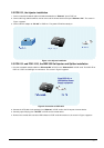
2.2 POE-151, the Injector installation
1. Connect a standard network cable from Switch/workstation to “Ethernet” port of POE-151.
2. Connect the long cable that will be used to connect to the remote device to the port “Ethernet + DC”. The screen in
Figure 1 appears.
3. Connect the AC adapter to “DC 48V” of POE-151. The power LED will be steady on.
Figure 1: the Injector installation
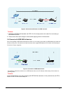
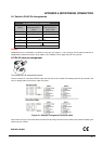
2.3 POE-151 and POE-151S, the IEEE 802.3af Injector and Splitter installation
1. Connect a standard network cable from “Ethernet+DC” of POE-151 to “Ethernet+DC” of POE-151S. The POE LED of
POE-151 / POE-151S will light on continuance. The screen in Figure 2 appears.
Figure 2: Connection to POE-150S
2. Connect the UTP cable in the package from “Ethernet” of POE-151S to the RJ-45 port of remote device.
3. Connect proper DC plug from “DC OUT” of POE-151S to remote device.
4. Power on the remote device and the LED indicator on POE-151S will remains on, the screen in Figure 3 appears.
From POE-151 or
IEEE 802.3af Power
Supply equipment