


Polycom RMX 1500 Hardware Guide
1-13
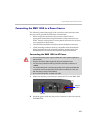
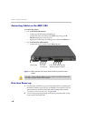
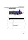
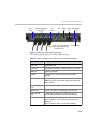
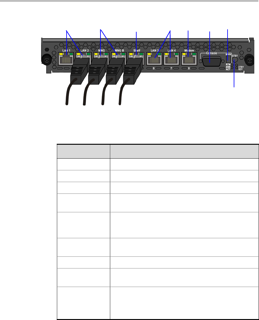
Figure 1-3 RMX 1500 RTM IP Rear Panel Layout
The following items appear on the RMX 1500 rear panel:
LAN 1-2
Ports
Shelf
connection
NA
Serial
Port
Standby button
LAN3, LAN 4 and the Serial
ports are only for debugging and not
for customer use
Modem
Port
Main RS 232
Switch
Signaling & Manage-
ment Ports
Table 1-5 RMX 1500 Rear Panel - RTM IP 1500 Component Description
Item Description
LAN 1 port Not Available (NA).
LAN 2 port LAN (Media) Connection. 1 Media IP address is available.
MNG port Signaling connection.
MNGB Management connection for Web Client and RMX
Manager.
LAN 3/4 ports Not Available (NA).
Note: LAN 3/4 are covered with a plastic cap that should
not be removed.
Shelf (Manager)
port
(Optional) Shelf Manager connection.
Modem port Internal IP connection, for debugging purposes only.
Serial (RS 232)
port
For debugging purposes only. Enables print-outs of
various LOGs from RTM IP 1500 and Card Manager.
MAIN/RTM Selection of the connection type for the RS-232 Port.
When the switch is up - the serial port connects to the
MPMx card.
When the switch is down, connects to the RTM IP.