


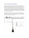
PHYSICAL CONNECTIONS AND GROUNDING
In order to connect the microphone to the Vortex Device, first connect the audio portion of the
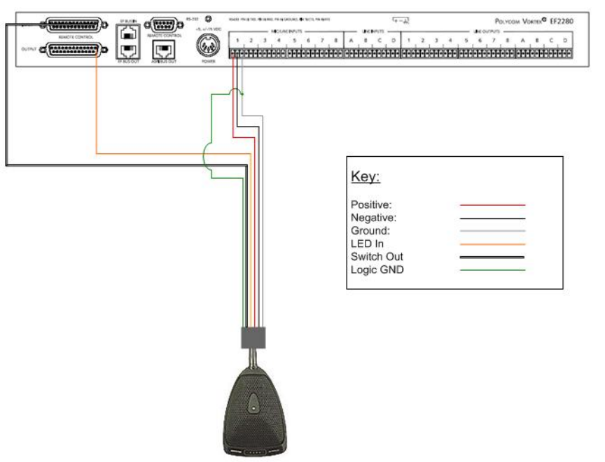
microphone to the Vortex Device: Connect the Positive conductor (Red) to the Positive terminal, the
Negative conductor (Black) to the Negative terminal, and the Ground wire (gray) to the Ground
terminal. Next, connect the SWITCH OUT (white) conductor to one of the Logic Input pins 1-24 and
then connect the LED IN (orange) conductor to one of the Logic Output pins 1-20 (Note that the
Logic Input and Outputs pins are fully programmable). Next, connect the LOGIC GND wire (green)
to the audio ground wire. Although, you can connect the LOGIC GND wire to one of the ground pins
on either the Logic Input or Logic Output port, both the Logic port ground pins and the audio ground
pin are tied to chassis ground of the unit.
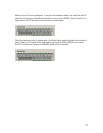
The drawing below shows how to perform the wiring. Note that for clarification purposes the
LOGIC GND wire is shown tied to the audio signal ground near the unit; however, this connection
may be made at the microphone itself so that you will only need a 4 conductor cable plus ground
wire to connect the microphone to the Vortex Device.
7