


Part 4
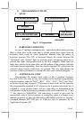
Fig.3-2
C. KEYTOP LAYOUT
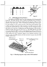
The basic layout of this programmable keyboard is a matrix with 6 rows
and 15 columns to provide maximum 84 positions for push keys with a 6
position control key and LED indicators. Within these 84 positions there is
four by four matrix below the control key area configured as numerical keypad.
This numerical keypad is a set of “numerical keys” which is composed of 12
numerical keys each is preprinted with one from the set of “0”, “00”, “.”, “1”,
“2”, “3”, “4”, “5”, “6”, “7”, “8” and “9” plus “-”, “+” and a double size
“Enter” key (ref. Fig. 3-7). However, there are means for the user to break the
monotony and to improve the efficiency in application of this programmable
keyboard.
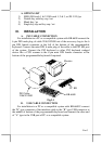
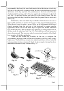
First of all, there are 4 legend sheets of different colors in the accessory
bag that the user may want to print the identification for each programmed key
into each cell of the sticker matrix and then stick each cell printed with the
identification onto the surface of the corresponding key top. A key cap from
the accessory bag can be snapped on the key top to protect the sticker (ref. Fig.
3-3). In this way the user may feel a lot easier in using the programmable
keyboard.
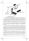
At the bottom of the programmable keyboard, the user may find an
adjustable key clip which can be used to pick up the key cap whenever
required (ref. Fig. 3-3). The two “feet” of the key clip should be pulled wide
for use with double key (ref. Fig. 3-4). It is advisable to use a flattop (minus
sign) screw driver to help getting the key top off when necessary (ref. Fig. 3-3
and 3-4 ).
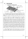
Whenever there comes the need to install a key top onto the
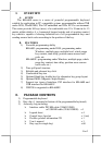
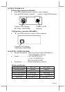
KB-6600U
Monitor
PC
USB Cable:
21863150800
PS2 KB or USB KB