


3 - 2
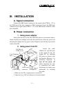
3. Select one I/O plate position on rear window of PC to install the I/O
plate of CCBLA-141.
4. Select one set of large 4 pin connector from the switching power
supply unit of PC and connect the male 4 pin connector of CCBLA-
141 to the connector from power supply. Connect the female 4 pin
connector of CCBLA-141 to the I/O device of PC such as a HDD if
necessary.
5. Assemble the case of PC back.
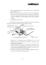
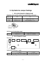
Then referring to drawing below to complete the basic power and signal
cabling. Note the PC should remain OFF during the connection.
1. Connect the 4 pin telephone plug of CCBLA-411 to the 4 pin
telephone jack on the I/O plate of CCBLA-141 which has been
mounted as described above.
2. Insert the DC plug of CCBLA-411 into the jack at the bottom of the
base of PD in the same way as the power adaptor. Let the cables come
out of the bottom of PD7100/7200 series through the opening at the
back of base so that the PD can stand securely.
3. Now the user may turn on the PC and the PD for application unless the
user wants to use PD for pass through purpose.
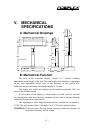
4 pin Telephone
jack of CCBLA-141
COM port (9 pin serial port)
Both to bottom
of PD
9 pin D connector
of CCBLA-372
4 pin Telephone plug of CCBLA-411
Rear side of PC