


Part 14
room also provides very good protection as long as the ambient temperature
remains below 30°C and the ventilation of the PST system is free. However,
should any accident happen and the sulfuric acid from the battery spills on skin
or clothing, wash immediately with water. If the acid comes in contact with
eyes, rinse eyes with large amount of clean water and see a doctor immediately.
A larger external battery may be connected to give an extended operation.
Please check your dealer about this capability when required.
WARNING:
If there are any signs of over charging or leakage of electrolyte
please contact your dealer immediately
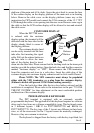
Printer DC Power Supply
This power supply is designed to support a Posiflex POS printer via
the right cable. Careless use of it will cause permanent damage.
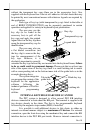
VGA Display Port
The VGA port in the PST terminal supports a 12 volt DC power to the
monitor inside the VGA signal cable. This may cause permanent damage to
any other monitor not designed to use this facility. Please use only a designed
monitor with the PST equipment. Consult your dealer if you have any doubt.
(Note: 12 volt DC power is available on pin 9 of the VGA connector and
is supported by the UPS function if the power management option is installed.)
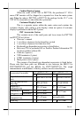
The video memory of this port shares the system memory. The video
memory size can be set in the CMOS setting to match the user’s application.
Customer Display Port
The customer display connector must always be occupied either by
the terminator plug (as supplied) or by one of the family of Posiflex customer
displays. Without this provision the COM1 port and the cash drawer control
(when power management option is installed) may fail to work correctly.
Serial Port – COM1
COM1 serial port must always be occupied by a suitable serial device
or COM1 terminator (as supplied). If this port is left vacant or connected with
something like a mouse the customer display port and the cash drawer control
(when power management option is installed) may fail to work correctly.
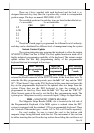
LED INDICATORS
Besides the LED on MSR unit there are another two LED’s on the
main unit in the area with the 6-position electronic key. The green LED at right,
called as the power LED, and the orange LED at left, called as the Standby
LED, together exhibit several different system statuses depending on whether
or not an UPS battery and the power management kit are fitted.
(a) Without an UPS battery the power LED lights to show that the system is
turned ON under presence of AC power. The standby LED indicates that