


Part 5
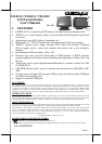
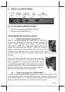
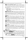
V. INPUT / OUTPUT PORTS
VI. AVAILABLE OPTION ITEMS
1. Side mount upgrade kit SD-400Z or KP-300
2. Wall mount kit (WB-6000V-B)
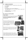
VII. HARDWARE INSTALLATION
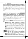
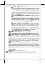
A. Option Side Mount Upgrade Kit
When a side-mount upgrade kit option such as SD-400Z is
ordered with the LM-8115 / TM-8115 / TM-8315 monitor, this
option is already installed in the delivery. No matter the kit
itself contains MSR only, finger print sensor only or both
options, the connection to the LM-8115 / TM-8115 / TM-8315
monitor is through an internal cable in right side cover of the
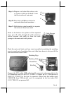
LCD/touch unit. Remove the 2 circled screws in the right
picture to remove the cover for side mount upgrade kit as viewed from back of
the panel.
Take out the cable inside this cover as arrowed in the right
picture here and connect it to connector inside the side
mount upgrade kit as circled in the same picture. Gently
arrange the excessive length of this cable back in the hole
and screw-fit it back to the position originally occupied by
the cover. Please reserve the cover if there is chance to
have the side mount kit removed in the future.
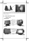
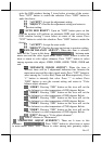
B. Cable Connections For TM/LM-8115
In order to settle the touch monitor properly in a point of sale system, all the
cable connections have to be routed through its base. Therefore, please observe
the procedures from A to C below to separate the main unit from the base
stand assembly after all cables in connection area disconnected.
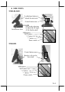
COM
(option RS232)
VGA
input
USB (B)
(to Host)
12 V DC
input
USB (A)
(to Devices)