


Part 8
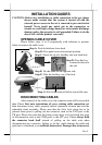
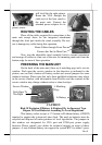
in squares in lower left picture and allow the main unit to slide down the
winding grooves in the wall mount backpack - originally the base box. The
stand assembly is not engaged in wall mount operation. Connect all cables
coming out of the backpack into the cable cover area of main unit.
The area required for wall mount application is determined by the
main unit dimensions and is 375 mm in width and 315 mm in height.
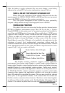
BASE MOUNT UPGRADE KIT
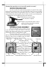
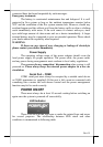
On rear edge of the stand assembly, there is a rear
connect cover. Either a 12” 2nd LCD display panel option
LM-6201 or a VFD customer display option PD-2501 can
be installed here for desktop mount application after
removing this cover. However, the 15” 2
nd
LCD display
can be installed without removing this cover.
12” 2
nd
LCD Panel Or Customer Display
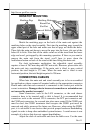
This rear connect cover can be removed
with metal chassis assembled in the base cover.
Refer to the inside view of the base unit after
removal of UPS battery bracket at right use a flat
head screwdriver to pick the plastic hook plate of the
rear connect cover from inside to remove the cover.
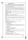
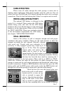
Fit the latest base of PD-2501 or LM-6201 to the
rear connect cover opening. For LM-
6201, please first route its cable through
this opening and have it pass the passage
arrowed in left picture. For PD-2501,
please have its cable go through the
normal cable exit (under the joint base) as in the right picture.
Fit 2 screws through washers to hold the joint tight. For low profile customer
display PD-305, the installation procedure is same. Remember to enable the +5
V DC supply in the COM port of main unit for PD-2501 or PD-305 or the
system. Please note that if the base (joining mechanism) of the PD or LM is of
older version for earlier large base of TP-59/70/82 series, there will be minor
styling discrepancy with the universal base of the system.
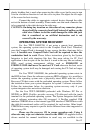
15” 2
nd
LCD Panel
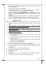
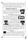
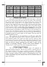
A bracket kit including a steel bracket and 2 types of
screws as in the left picture will be provided with the 15” 2
nd
LCD panel. Use 3 smaller screws to fix the bracket to outside of
the bottom plate from inside as circled in the below left picture that is the
bottom view of the base stand. Then use the 4 larger screws to fix the monitor
support rod from bottom as arrowed in the same picture. The overall assembly