


Installation Instructions Page 5
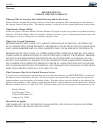
GB-PIPE1
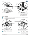
Mounting Hole
Spring Loaded
Nuts
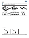
Step 6. Lift the equipment tray into position.
Upper Plate
Step 7. Line up the mounting holes with the
threaded shaft of the spring loaded nuts.
Step 8. Once the holes are lined up, press down
on the spring loaded nuts and tighten.
Step 9. Insert and tighten two (2) M4 x 10mm
security screws on the upper plate.
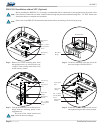
Electronic Components
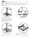
1-1/2” NPT Installation
The NPT must rotate onto the
equipment tray four (4) complete
rotations.
Step 2. Use an M3 security wrench to tighten the
set screw.
Step 3. Attach projector mount to NPT.
1-1/2” NPT
1-1/2” NPT
Equipment Tray
Set Screw
Step 1. Place the threaded end of the 1-1/2” NPT
into the plate hole.
Plate Hole
Before attaching the lower 1-1/2” NPT, it is strongly recommended that all connections in the equipment tray be made at
this time. Once the connections are made, feed the cables through the plate hole and then through the 1-1/2” NPT. Please
read instructions below to complete the installation.
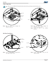
M4 x 10mm
Security
Screws
Please follow the instructions
included with the mount to complete
this step. If using a PDS Series mount,
connection may be made directly to
the bottom of the equipment tray.