


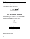

Printer Configuration
Note: Be careful when changing switch settings. Carefully use a pointer on the lever of the switch you wish to
change. DO NOT use a lead pencil as this may contaminate the switch. DO NOT use a screw driver or
apply excessive force.
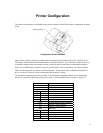
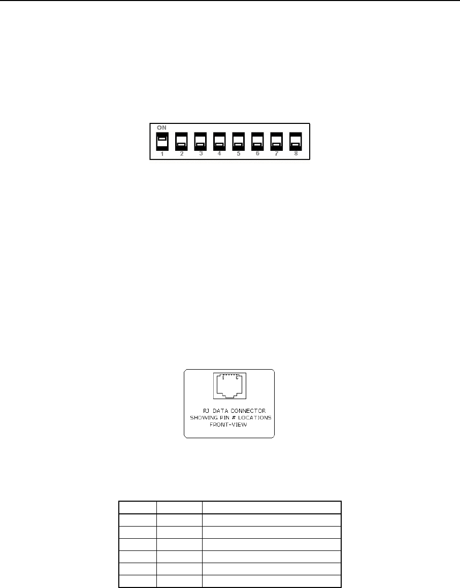
The following diagram shows switch settings for IrDA communications.
Sample Switch Setting
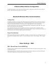
Serial RS-232C Interface Configuration
In order for the printer to receive data using the RS-232C interface, configuration switch SW1 must be in the
Off Position. Additionally, the baud rate on switches SW2 & SW3, and the parity on switches SW6 & SW7
must be set to match the settings on the host computer.
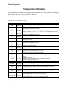
The RS-232C Interface signals are provided on a 6 Pin RJ type data connector located on the side of the printer.
A diagram of the connector and a table showing the pin assignments are shown below.
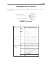
Serial RS-232C Connector Pin Out
Pin # Signal Description
1 COM Logic Common
2 TXD Transmit Data (From Printer)
3 RXD Receive Data (From Host)
4 CTS Clear To Send (From Printer)
5 COM Logic Common
6 RTS Request To Send (From Host)
Serial RS-232C Interface signals
The serial interface supports hardware handshaking using the RTS and CTS signals, and supports software
handshaking using the XON/XOFF characters.
12