Pin No Signal Pin No Signal Pin No Signal
1 T.M.D.S. Data 2 - 11 T.M.D.S. Data 1 / 3 Shield 21 -
2 T.M.D.S. Data 2 + 12 - 22 T.M.D.S. Clock Shield
3 T.M.D.S. Data 2 / 4 Shield 13 - 23 T.M.D.S. Clock +
4 - 14 +5V Power 24 T.M.D.S. Clock -
5 - 15
Ground (+5V, Analog H/V Sync.)
6 DDC Clock 16 Hot-Plug Sense
7 DDC Data 17 T.M.D.S. Data 0 -
8 Analog V. Sync. 18 T.M.D.S. Data 0 +
9 T.M.D.S. Data 1 - 19 T.M.D.S. Data 0 / 5 Shield
10 T.M.D.S. Data 1 + 20 -
Pin No Signal Pin No Signal Pin No Signal
1 Video input Red 9 -
15
RGB IN 1: SCL(DDC)
2 Video input Green 10 Ground RGB IN 2: -
3 Video input Blue 11 - RGB OUT: -
4 -
12
RGB IN 1: SDA(DDC)
5 Ground RGB IN 2: -
6 Ground Red RGB OUT: -
7 Ground Green 13
H. sync./ Composite sync.
8 Ground Blue 14 Vertical sync
TECHNICAL - 1
TECHNICAL
TECHNICAL
TECHNICAL
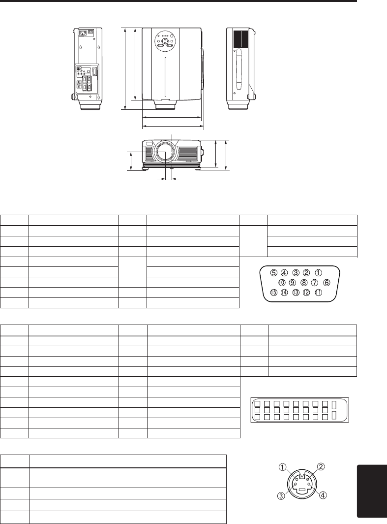
Dimension Diagram
395
350
139
144
88
289
308.5
30.5
Unit : mm
3. Mini Din 4-pin Connector (S-VIDEO)
Pin No Signal
1
Color:0.286Vp-p (NTSC, burst signal),75Ω terminator
0.3Vp-p (PAL/SECAM, burst signal),75Ω terminator
2 Brightness:1.0Vp-p, 75Ω terminator
3 Ground
4 Ground
Signal Connector Pin Assignment
1. D-sub 15-pin Shrink Connector (RGB IN 1/RGB IN 2/RGB OUT)
2. Digital Receptacle Connector (DVI)
12345678
9 101112131415
16
17 18 19 20 21 22 23 24


