


Replacement Guide Fibre Channel Switch Power Supply
Corporate Headquarters QLogic Corporation 26650 Aliso Viejo Parkway Aliso Viejo, CA 92656 949.389.6000 www.qlogic.com
International Offices UK | Ireland | Germany | France | India | Japan | China | Hong Kong | Singapore | Taiwan
Preparation
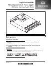
The power supplies are hot pluggable and
interchangeable. When removing or replacing a
power supply on an operating switch, be sure the
Heartbeat LED is showing the normal one blink
per second. This allows the switch to continue
operating correctly while removing and replacing
power supplies.
1. Heartbeat LED
Removing a Power Supply
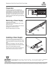
Unplug the power supply.
Loosen the two knurled fasteners with a cross-
head screw driver.
Grasp the power supply handle and pull firmly to
disengage the modular connector.
Slide the power supply out of its bay.
1. Knurled fastener 2. Handle
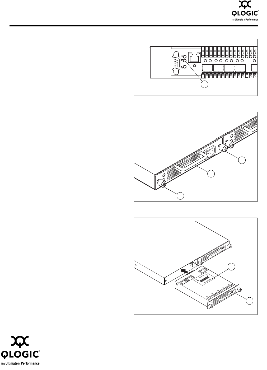
Installing a Power Supply
Confirm that the new power supply air flow
direction is compatible with the old power supply.
The air flow direction is noted on the part number
label.
With the AC receptacle on the right, slide the
power supply into the bay until it is firmly seated.
Secure the knurled fasteners by hand.
Plug the power cord into the AC receptacle and
confirm that the air flow direction is correct.
1. Part number label 2. AC receptacle
L
AL AL AL
AL
0
1
2
3
4
1
1
1
2
1
2
© 2011 QLogic Corporation. Specifications are subject to change without notice. All rights reserved worldwide. QLogic and the QLogic logo are registered trademarks of QLogic Corporation.
All other brand and product names are trademarks or registered trademarks of their respective owners. Information supplied by QLogic Corporation is believed to be accurate and reliable.
QLogic Corporation assumes no responsibility for any errors in this brochure. QLogic Corporation reserves the right, without notice, to make changes in product design or specifications.