


2
Instructions for the DDI-3 DataPort Accessory Card
I. INTRODUCTION
The DDI-3 DataPort Accessory Card converts a QSC amplifier’s DataPort to an eight-position terminal block, providing
convenient access to the pins of the amplifier’s DataPort; this is useful for connecting input signals or implementing a
remote on/off (standby) system without using a DataPort cable. Four solder pads provide access to the amplifier’s output
voltage and current monitors.
QSC ISA, CX, DCA, SRA, PowerLight, and PowerLight 2 Series amplifiers feature a DataPort for every two audio channels.
Therefore, one- and two-channel models have one DataPort, while four-channel models have two and eight-channel models
have four. On the four- and eight-channel CX and DCA models, only the DataPort for channels 1 and 2 has the power supply
standby feature. ISA models do not have power supply standby or output voltage and current monitoring.
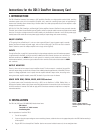
ON/OFF CONTROL
A TTL-type logic
low
at DataPort pin 2, such as a short to ground (Figure 2), puts the power supply in standby.
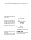
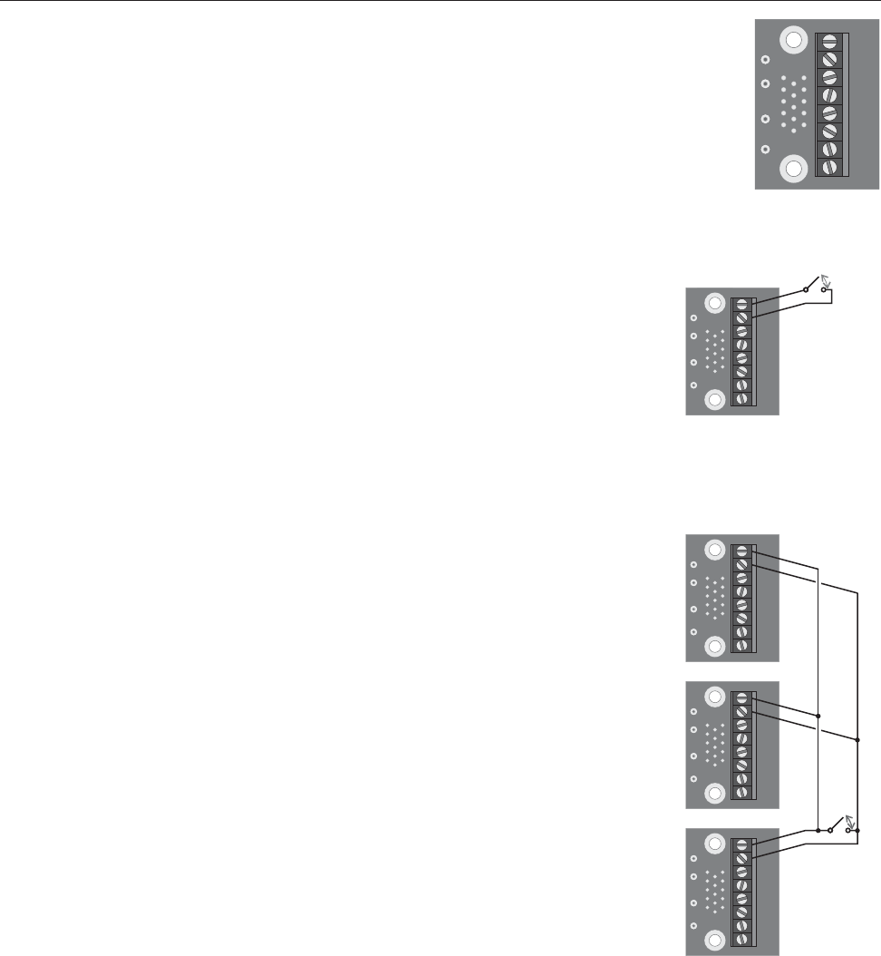
Opening the short will restart the power supply, with no inrush current surge. The DDI-3 now has an isolation
diode to allow the control of multiple amplifiers with a single switch (Figure 3).
INPUTS
Through its DataPort, an amplifier’s input sensitivity (the input voltage required to reach full rated output power)
is approximately 3 volts RMS, at full gain and with an 8Ω load on each channel. Use the + and - terminals for
balanced connections; the AGND terminal is audio ground, for conecting a cable shield when necessary. For
unbalanced connections, connect the signal conductor to the + terminal and the cable shield to both the AGND
and - terminals.
OUTPUT MONITORS
There is a VMON and an IMON output for each amplifier channel. The VMON output is a sample of the amplifier
channel’s output voltage, scaled so that full output into an 8Ω load equals approximately 3 volts RMS. The I
MON
output is a voltage proportional to and in phase with the amplifier channel’s output current; the scaling varies
among the various amplifier models; contact QSC for details if you wish to use this feature.
USAGE WITH DCM, CM16A, BASIS, AND QSControl.net
To maintain power on/off functionality when using a DDI-3 on the DataPort of a DCM, CM16a, Basis, or
QSControl.net product, solder a wire jumper across the diode located on the same side of the circuit board that
the HD15 connector is mounted. This does not apply to DDI-3 interfaces mounted on amplifiers or on amplifier-
mounted accessories.
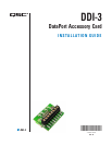
STBY
CGND
CH2+
CH2-
AGND
CH1+
CH1-
AGND
VMN1
IMN1
IMN2
VMN2
STBY
CGND
CH2+
CH2-
AGND
CH1+
CH1-
AGND
VMN1
IMN1
IMN2
VMN2
Run
Standby
STBY
STBY
STBY
CGND
CGND
CGND
CH2+
CH2+
CH2+
CH2-
CH2-
CH2-
AGND
AGND
AGND
CH1+
CH1+
CH1+
CH1-
CH1-
CH1-
AGND
AGND
AGND
VMN1
VMN1
VMN1
IMN1
IMN1
IMN1
IMN2
IMN2
IMN2
VMN2
VMN2
VMN2
Run
Standby
Figure 3. On/off control of
several amplfiers with a single
switch
II. INSTALLATION
The DDI-3 kit (QSC part # SG-000235-00) includes these items:
DDI-3 board
Two #4-40 × ¼” black screws
Installation guide
Use this procedure to install the DDI-3:
1. Turn off the amplifier.
2. If you are using the output voltage or current monitoring features, solder the wires to the appropriate pads on the DDI-3 before attaching it
to the amplifier.
3. Plug the DDI-3 into the amplifier’s DataPort. Use the two screws included to secure it; do not overtighten them.
Figure 1. The DDI-3
Figure 2. On/off control of a
single amplifier