


Hardware Description (continued)
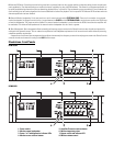
Rear Panel
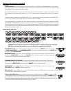
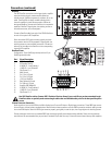
Amplifier DataPorts: Each DataPort provides two channels of audio from the DCM to the QSC amplifier input, as well as current
and voltage monitoring of the amp’s loudspeaker outputs. Remote power on/standby control of the amplifier is also provided, allow-
ing the DCM to act as a master system power controller.
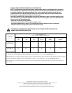
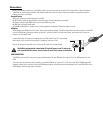
Use only QSC DataPort cables. Custom-length DataPort cables with individually shielded-pair construction are available from QSC’s
Technical Services Group. Stock lengths include 1, 2, 3, 4, 5, 6, 10, and 20 feet and are designated DPC-x (where “x” is the length in
feet).
The maximum output configuration of the DCM 10/10D is a 6 ch / 2-way. The maximum output configuration of the DCM 30/30D is
an 8 ch / 4-way. In addition, many parallel outputs are provided for additional flexibility.
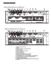
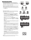
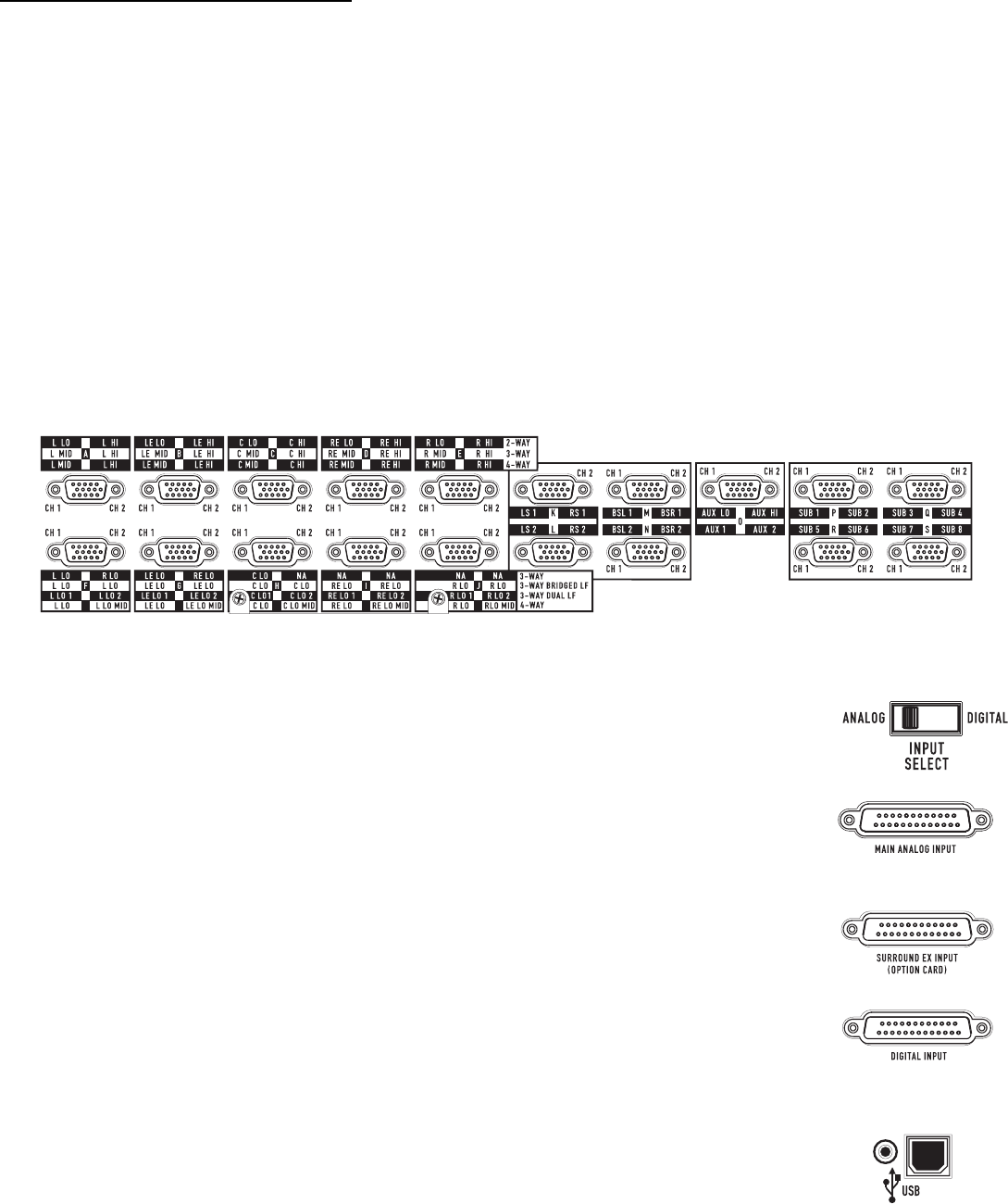
The rear panel labelling on the DCM has all of the information required by an audio installer. When starting, write down the EXACT
LOUDSPEAKER CONFIGURATION (for example, 8 channel, tri-amp with 2 surrounds and 4 subs). Now you can follow the rear panel
text which shows both channel position (L or C or R, etc) and the frequency output (LO, MID, HI, etc). Connect the L-LO output to the
correct amplifier driving the left positional loudspeaker’s low frequency transducer, and L-HI to the amplifier driving the same loud-
speaker’s high frequency transducer, etc.
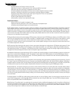
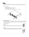
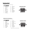
DCM 30 DataPort Illustration:
WARNING: Incorrect frequency connections can damage transducers. Physically verify proper connections
AND listen to each individual transducer at very low volume before applying full audio power.
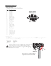
INPUT SELECT Switch: Use this switch to select the input source of the DCM. In the ANALOG position, input is from
the MAIN ANALOG INPUT ( and the SURROUND EX INPUT, if this option is installed). If the switch is in the DIGITAL posi-
tion, input is from the DIGITAL INPUT.
MAIN ANALOG INPUT: Connect this to the cinema processor’s output. This is the input source of all film sound into the
DCM unit if the INPUT SELECT switch is set to the ANALOG position. The 25-pin connector is an industry standard type
and pinout; cables are available from cinema supply houses.
SURROUND EX INPUT (OPTION CARD): This input provides additional inputs when using a Dolby CP650 with the
Cat.790 or Cat.791 option cards. The surround, backwall surround, and left extra/right extra channels are input through
this connector. The INPUT SELECT switch must be set to ANALOG in order to use this connection.
DIGITAL INPUT: If using a Dolby CP650 with Cat.778 option, connect the CP650 digital output to this connector. Set the
INPUT SELECT switch to DIGITAL to select the digital input.
USB Connection: Connect to USB port on the host PC. Communication between the DCM Manager software (running on the host
PC) and the DCM is routed throught this connection.
Firmware Update Mode Select: This recessed push button switch is located directly left of the USB port. To place the DCM
in firmware update mode, press inward and hold the switch in the depressed position while turning the AC POWER switch on.
Use a small tool, such as the end of a paperclip wire or similar object to depress the switch. The AC power must be off before
initiating this sequence. Release the switch once the AC power has been applied. The DCM Manger software may then be used
to continue the update procedure (refer to the software help file for details).