


Connections (continued)
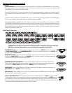
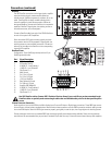
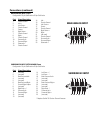
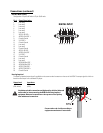
DIGITAL INPUT Pinout
Configuration: 25-pin SubD male to 25-pin SubD male.
Pin #
Signal Description
1 (not used)
2 (not used)
DIGITAL INPUT
3 (not used)
4 (not used)
5 (not used)
6 (not used)
7 AES1 (L/R) OUT +
8 AES3 (Ls/Rs) OUT +
9 Chassis Ground
10 X1/2 OUT +
11 Chassis Ground
12 (not used)
13 (not used)
14 Chassis Ground
15 AES1 (L/R) OUT -
16 AES3 (Ls/Rs) OUT -
17 X1/2 OUT -
18 Chassis Ground
19 (not used)
20 (not used)
21 AES4 (Bsl/Bsr) OUT -
22 AES4 (Bsl/Bsr) OUT +
23 AES2 (C/SW) OUT -
24 AES2 (C/SW) OUT +
25 Chassis Ground
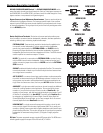
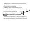
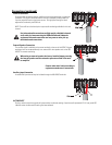
Hearing Impaired
The Hearing Impaired output signal is available on the screw terminal connector on the rear of the DCM. The output signal is similar to
levels that are output from a standard CD player.
Output Level
Impedance
-11.8 dBu 50 ohms
(200 mVrms) (±5%)
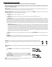
Use balanced audio connections and high-quality, shielded, balanced
audio cable for interconnecting the DCM and Hearing Impaired
equipment. Balanced connections are less prone to noise pick-up
than unbalanced connections.
Connect other end of cable according to
equipment manufacturer’s instructions.