


7 External Connections
The DSCLP-200/300 provides four differential communication signals per
channel. The two output signals are Transmit Data (TxD) and Auxiliary Output
(AUXOUT). The two input signals are Receive Data (RxD) and Auxiliary Input
(AUXIN). A ground signal is also provided.
The available input signals for AUXIN are Clear To Send (CTS) and the
Receive Clock (RCLK). The available output signals for AUXOUT are Request
To Send (RTS), the Transmit Clock (TCLK), and the AUXIN signal (for
loopback). Either half-duplex or full-duplex operation can be selected for each
communications channel. Auto-Toggle is also jumper selectable .If half-duplex
operation is selected, one of the UART's signals (either DTR or RTS) is used to
enable the transmitter drivers. The inverse of the transmitter enable can be used
to enable the receiver drivers.
Factory-installed resistors allow for signal line termination in compliance
with the RS-422 and RS-485 standards. The desired termination can be selected
or removed per port by applying a jumper.
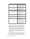
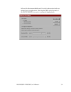
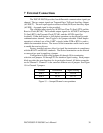
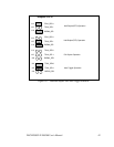
Configuration is done using jumpers J6 through J9 for termination
selection, and jumpers J10 through J23 for interface signal routing. Each jumper
block provides the same functions for its particular channel. All below examples
are for Channel 1. Channel 2 is the same but different sets of jumpers. See Figure
15 for Channel 2 jumpers.
J17-23J8, J9Port 2
J10-16J6, J7Port 1
Signal routingTermination Channel
Figure 15 --- Jumper/Channel correspondence
DSCLP/SSCLP-200/300 User's Manual 38